
Relay Toggle Circuit Using a 555 Timer circuit
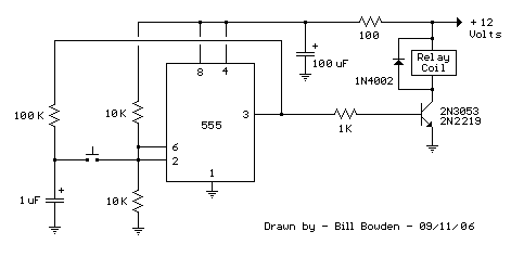
The described circuit utilizes a 555 timer in a bistable configuration, allowing it to function as a toggle switch for a relay. The relay can control larger loads and is often used in applications where electrical isolation is needed between the control circuit and the load.
In this circuit, the two 10K resistors connected to pins 2 and 6 ensure that these pins are biased at half the supply voltage, which is essential for the proper operation of the timer. When the button is pressed, it momentarily connects the capacitor voltage to the trigger input (pin 2). This causes the timer to switch its output state.
The 100K resistor plays a crucial role in controlling the charging time of the capacitor. When the output of the 555 timer is high, the capacitor charges through this resistor, leading to a gradual increase in voltage across the capacitor. Once the voltage across the capacitor reaches a certain threshold, the output of the timer switches to low, allowing the capacitor to discharge. This cycle can repeat with each button press, effectively toggling the state of the relay.
The relay, connected to the output pin, can be used to switch on or off additional circuits or devices, providing a practical application for the timer circuit. Care should be taken to select a relay that can handle the load current and voltage requirements of the connected device. Additionally, appropriate flyback diodes should be used across the relay coil to protect the timer from voltage spikes generated when the relay is de-energized.
This configuration offers a simple yet effective method for creating a toggle switch with the added benefits of isolation and control over higher power devices.This 555 timer circuit toggles a relay when a button is pressed. Pins 2 and 6, the threshold and trigger inputs, are held at 1/2 the supply voltage by the two 10K resistors. When the output is high, the capacitor charges through the 100K resistor, and discharges when the output is low.
When the button is pressed, the capacitor voltage is applied to pins 2 and 6 which causes the output to change to the opposite state.. 🔗 External reference
Related Circuits

Very simple and useful circuit for communication between two persons. The Q1 is used to amplify the weak output signal of the speaker when one pushes his (her) side push-button to speak. The base-common configuration of the Q1 pre-amplifier...
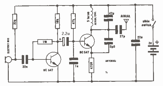
This is just one of the many bugging devices available on the eavesdropping market. The range includes pen and pencil holders, trophies, framed pictures, and office furniture with false bottom drawers. These products are readily sold to fledgling companies,...
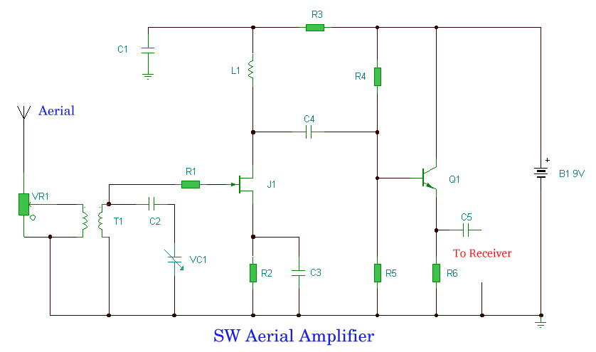
The challenge in amplifying weak radio signals lies in the simultaneous amplification of noise. The quality of the received signal is influenced by the level of background noise, which may include man-made interference or static. In this design, the...
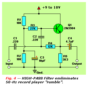
The final article on bipolar junction transistors (BJT) presents a variety of circuits, some practical and others more experimental. These circuits are capable of amplifying signals, filtering high and low frequencies, generating white noise, and flashing lamps. They can...
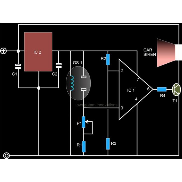
A straightforward smoke detector circuit has been presented through a schematic diagram, which can be easily constructed and installed in an area for essential detection purposes. The circuit utilizes the versatile FIGARO TGS 813 gas sensor as the primary...
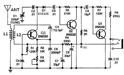
All coils are designed using an inch diameter PVC pipe with 20-gauge insulated hookup wire. L1 requires 6 turns, while L2 requires 14 turns. Additional turns can be added or subtracted from L1 or L2 (or C2 can be...
Warning: include(partials/cookie-banner.php): Failed to open stream: Permission denied in /var/www/html/nextgr/view-circuit.php on line 713
Warning: include(): Failed opening 'partials/cookie-banner.php' for inclusion (include_path='.:/usr/share/php') in /var/www/html/nextgr/view-circuit.php on line 713