
Interface multiple keys with one wire and save pins of MCU
To select resistors, the pull-up resistor must be chosen first; a common value is 10 kΩ. Some ADCs may require lower input resistance to achieve the desired conversion speed. However, for low-power applications, increasing the pull-up resistance can reduce conversion speed. The voltage must be divided into even intervals with keyboard resistors. If B represents the size of the interval, K is the number of keys, and N is the number of ADC bits, then the equation is B = 2^N / K. For a 10-bit ADC with 8 keys, B equals 1024 / 8, resulting in 128 voltage steps per interval. The key value is positioned in the middle of the interval, calculated as XK = K * B / 2. The resistor values needed for each key can be determined using the formula RK = (XK * R1) / (2^N - XK). Consequently, the first resistor value is 667 Ω, the second is 23080 Ω, and so on. The closest values are displayed in the schematic. In this scenario, with 8 keys, the minimal accuracy for resistors is 1/8, or 12.5%, thus 5% accuracy resistors are adequate. For configurations with more keys, such as 16 or more, selecting resistors with 1% accuracy is advisable. This keyboard design is suitable for low-power devices since no current is drawn when buttons are not pressed. The ADC input can be configured to activate interrupts when any button is pressed, allowing the microcontroller to remain in standby mode. This solution is particularly effective with AVR Tiny microcontrollers, such as the Attiny15L, which have a total of 8 pins, requiring only one pin for a larger number of keys.
The one-wire keypad circuit design is an efficient method for interfacing multiple buttons with minimal pin usage on a microcontroller. By employing a voltage divider network, the circuit effectively translates button presses into distinct voltage levels that the ADC can interpret. The choice of resistor values is critical to ensure accurate readings, with the arrangement allowing for a clear distinction between the voltage levels corresponding to different keys. The capacitor included in the design plays a vital role in filtering out transient signals caused by mechanical bounce, enhancing the reliability of key detection. This approach reduces the complexity of wiring and simplifies the design of user interfaces in embedded systems, making it particularly advantageous for compact or resource-constrained applications. The overall architecture promotes low power consumption, which is essential for battery-operated devices, thereby extending the operational life of such systems.Usually keyboard is connected by using matrix type of connection a‚ rows and columns. For instance for 12 button keyboard wee need 3 4 digital inputs of microcontroller. There is a way to build keyboard and connect to microcontroller using only one wire. For this we will need only signal wire, power and ground and of course microcontroller must have analog ADC input. One wire keypad circuit: Circuit is nothing more than simples digital to analog converter. Microcontroller reads voltage from signal line and calculates which key is pressed. Lets see how it works. If no any of keys have been pressed, then line has voltage equal to power source. If any key is pressed, voltage divider divides the voltage according to resistor connected to this button. Capacitor works as filter of mechanical noise during button contact. This way microcontroller can check the voltage of signal line and calculate which button is pressed. How to choose resistors For this first we have to select pull up resistor first. In this example is 10kOm. Some ADC may require lower input resistance to maintain desired conversion speed. But if you want to make really low power application, you can increase pull-up resistance and decrease conversion speed.
Further we have to divide voltage in even intervals with keyboard resistors. If B size of interval, K a‚ number of keys, N a‚ number of ADC bits, then: B=2N/K. If ADC resolution is 10 bit and wee have 8 keys, so wee will have B=1024/8=128 voltage steps for one interval. As key value is in the middle of interval then its value will be: XK=KB B/2. Resistor values needed for each key: RK=(XKR1)(2N-XK). This is why first resistor has value of 667Ohm, second 23080Ohm and so on. Closes values are displayed in schematic. In this case for 8 keys minimal accuracy of resistors is 1/8=12. 5% so in reality 5% accuracy resistors will do the job. If there will be more keys used like 16 and more, then choose more accurate resistors like 1%. This keyboard can be used in low power devices because while buttons isn`t pressed there is no current required.
ADC input can be configured as interrupt activated when any button is pressed. Otherwise microcontroller can be in stand by mode. I find this handy solution with AVR Tiny microcontrollers like Attiny15L where overall number of pins is 8. And for big number of keys you will only need one pin. We aim to transmit more information by carrying articles. Please send us an E-mail to wanghuali@hqew. net within 15 days if we are involved in the problems of article content, copyright or other problems.
We will delete it soon. 🔗 External reference
Related Circuits
The circuit utilizes a dual sound multi-frequency encoding signal to modulate the emitted carrier frequency, forming a DTMF encoding wireless calling system. It incorporates the DTMF encoding circuit UM97085 and the decoding circuit YN9101 to create a micro wireless...
Its an adaptation of the 2X 16 LCD project, by adding a ferrite loop antenna, two resistors, and a capacitor. Here the display shows the output of the 10 bit scanning voltmeter with Minimum Mass Wireless Coupler. Both the...
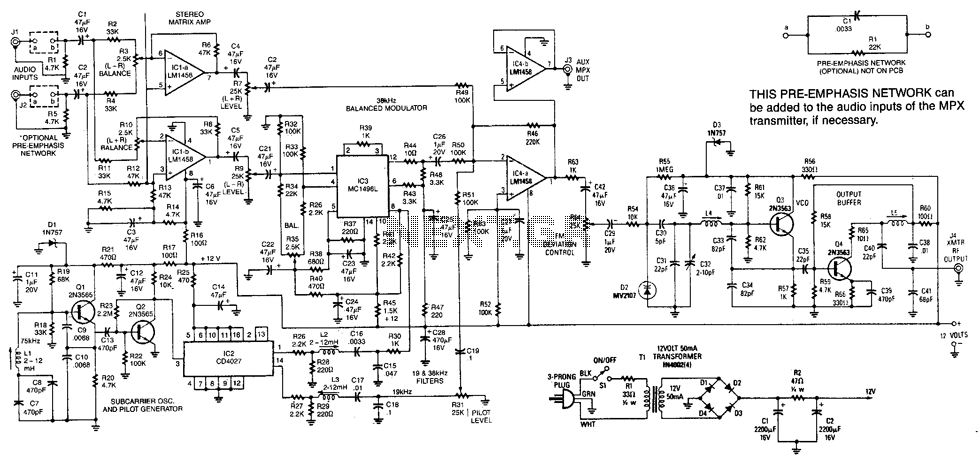
This transmitter has a range of up to 100 feet. It generates a complete multiplex stereo signal and is useful for cordless headphone applications in which an inexpensive socket stereo receiver can be used. It can also be used...
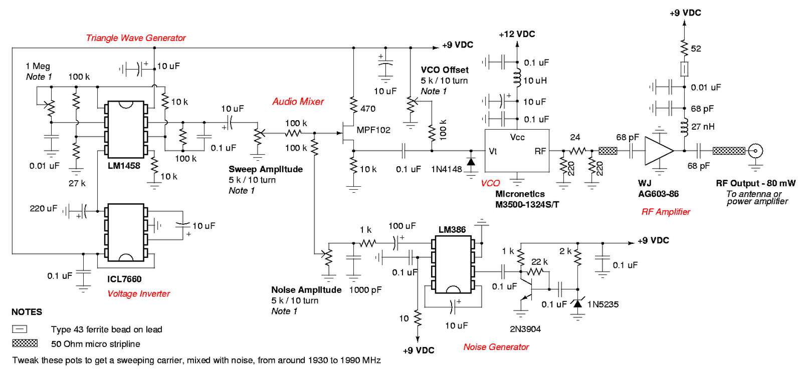
An admirable DIY GSM jammer or cellular mobile phone jammer schematic diagram designed for use with GSM1900, operating within the frequency range of 1930 MHz to 1990 MHz. The GSM1900 cellular mobile phone system is utilized in the USA,...
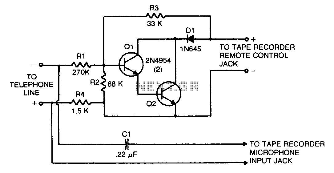
This circuit transforms a tape recorder into a fully automatic device for recording telephone conversations without requiring an external power source. The voltage at the switch terminals of the tape recorder is applied to a pair of Darlington-connected transistors,...
Even if the circuit is simple, it complies with all conditions regarding distortion and frequency response. The input resistance is 250K ohms, and it can drive loads ranging from 100 ohms to 2K ohms. The described circuit is a fundamental...