
Wireless LCD Display (AT90S2313)
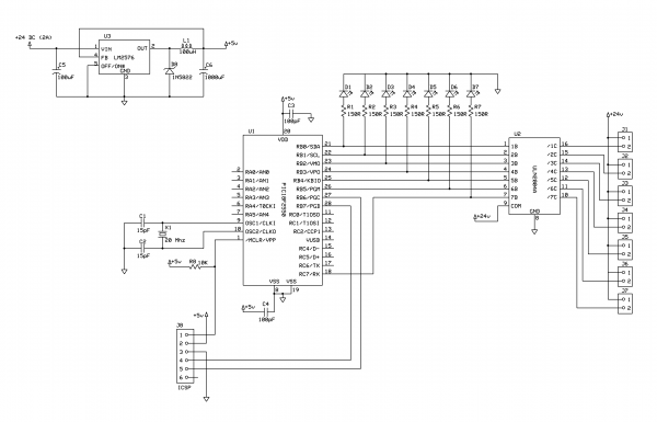
The described project integrates a 2X16 LCD display with a ferrite loop antenna to enhance wireless communication capabilities. The addition of two resistors and a capacitor serves to optimize the circuit performance, ensuring stable operation of the display while receiving signals from the Minimum Mass Wireless Coupler. The ferrite loop antenna is crucial for capturing signals in the vicinity, allowing for the wireless transmission of data from a scanning voltmeter.
The firmware adaptation is a significant aspect of this project. It modifies existing code from a serial interface originally intended for the Truly MTC-C162DPLY-2N LCD. The modified firmware incorporates additional functionality to handle data retrieval from both the UART and the Minimum Mass Wireless Coupler. This dual-source capability allows the display to present data from multiple inputs simultaneously or switch between sources as needed.
The circuit design includes careful consideration of the connections between the LCD, the wireless coupler, and the antenna. The resistors are likely used for current limiting or voltage division, while the capacitor may be employed for signal smoothing or filtering. The overall design promotes a user-friendly interface, enabling users to read voltage measurements without direct physical connections to the measuring devices. By placing the display unit near the signal source, users can conveniently access real-time data, enhancing the versatility and application range of this electronic project.Its an adaptation of the 2X 16 LCD project, by adding a fettite loop antenna, two resistors, and a capacitor. Here the display shows the output of the 10 bit scanning voltmeter with Minimum Mass Wireless Coupler.
Both the ferrite loop antenna and the scanning voltmeterare described elsewhere on this site. This project is an adaptation of A serial interface for the Truly MTC-C162DPLY-2N. Similar to the Minimum Mass Wireless Coupled Frequency Meter project, the firmware was made by adapting that from a finished project. In this case, the part of the code that makes the calls to check for and retrieve data from the UART was modified to also makes calls to check for and retrieve data from the Minimum Mass Wirelss Coupler.
In this way, the dispaly can accept and display input from either source, or both at the same time if there was a reason to do that. The benefit is that the display can be used with various other devices, such as the scanning voltmeter without the need to make a physical connection.
Merely place the display near the gizmo sending the signal and read the result. 🔗 External reference
Related Circuits
Each part of the LCD has an individual counter, latch, decoder, and driver. The pumping signal is fed back to the motherboard of the LCD. When the display section is disconnected, the phase and amplitude of the motherboard and...
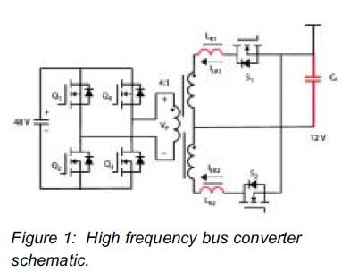
This article demonstrates that enhancement mode GaN transistors facilitate substantial efficiency enhancements in resonant topologies and provides a practical example of wireless power transmission. Enhancement mode Gallium Nitride (GaN) transistors are semiconductor devices that have gained attention for their ability...
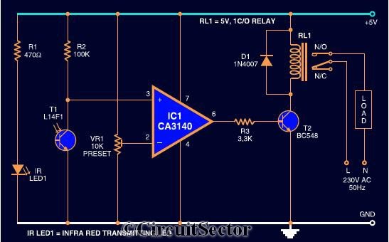
The circuit diagram presented is a highly sensitive wireless relay switch designed to control home appliances such as flush systems and hand dryers. This wireless switch operates without the need for a remote control. It functions by simply moving...
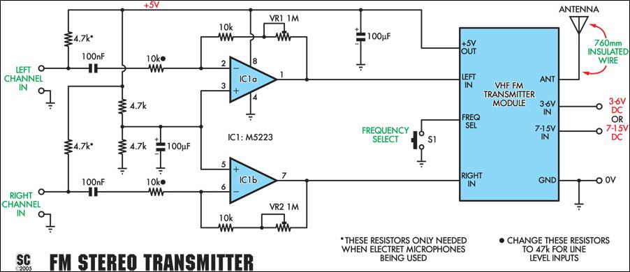
This stereo FM wireless microphone serves as an excellent audio link. Testing revealed a reliable range exceeding 50 meters. It is distinct from previous wireless microphones due to its stereo capability, which delivers unexpectedly high-quality sound. The range was...
Another method of testing the received signal strength on a Symphony-based wireless network is with a homebrew signal meter. The National LMX2240 Intermediate Frequency Receiver has a pin called "RSSI Out." RSSI stands for Relative Signal Strength Indicator and...
This project demonstrates the construction of a simple LED light string display utilizing seven 24V LED light strings. The project was designed for Christmas 2009 to adorn a balcony with lights. The light strings are widely available, particularly in...