
interfacing lcd atmega32 microcontroller atmel studio
The library provides functions for cursor control and character writing. The functions `Lcd8_Set_Cursor()` and `Lcd4_Set_Cursor()` set the cursor position on the LCD by specifying the desired row and column. The functions `Lcd8_Write_Char()` and `Lcd4_Write_Char()` write a single character to the LCD, incrementing the cursor position accordingly. The functions `Lcd8_Write_String()` and `Lcd4_Write_String()` are used to display strings on the LCD, advancing the cursor by the length of the string plus one.
The code snippet demonstrates the initialization and usage of the LCD in both 8-bit and 4-bit modes. It sets the data direction registers for ports D and C to output, initializes the LCD, and enters a loop where it displays a scrolling message. The scrolling effect is achieved by shifting the displayed text left and right, with a brief delay between shifts. The program concludes by clearing the display and writing individual characters.
The library is defined with specific macros for pin assignments, including data pins D0 to D7 and control pins RS and EN. The clock speed for the microcontroller is defined as 16 MHz, ensuring proper timing for operations. The header file for the LCD library can be downloaded from the referenced article, allowing users to easily implement the functions in their projects.
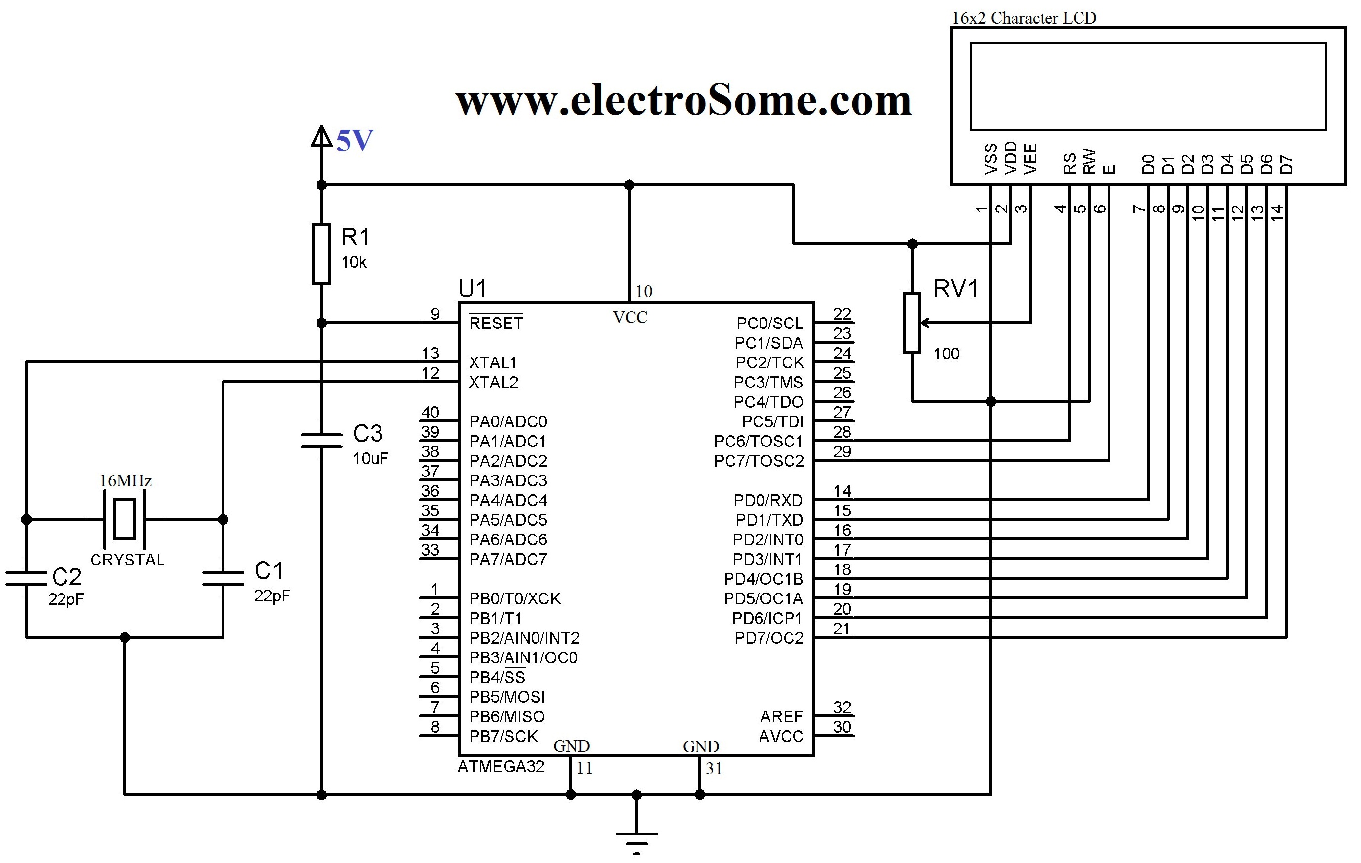
This comprehensive approach to interfacing the 16G-2 LCD with the Atmega32 microcontroller provides a robust solution for displaying information in various electronic applications, making it an invaluable resource for hobbyists and engineers alike.LCD (Liquid Crystal Display) is an electronic display which is commonly usednowadaysin applications such as calculators, laptops, tablets, mobile phones etc. 16G—2 character LCD module is a very basic module which is commonly used by electronic hobbyists and is used in many electronic devices and project.
It can display 2 lines of 16 character and each character is displayed using 5G—7 or 5G—10 pixel matrix. Interfacing 16G—2 LCD with Atmega32 Atmel AVR Microcontroller using Atmel Studio is bit complex as there is nobuiltin libraries. To solve this difficulty we developed a LCD library which includes the commonly used features. Just include our header file and enjoy. You can download the header file from the bottom of this article. 16G—2 LCD can be interfaced with a microcontroller in 8 Bit or 4 Bit mode. These differs in how data and commands are send to LCD. In 8 Bit mode character data (as 8 bit ASCII) and LCD command aresentthrough the data lines D0 to D7.
That is 8 bit data is send at a time and data strobe is given through E of the LCD. But 4 Bit mode uses only 4 data lines D4 to D7. In this 8 bit data is dividedintotwo parts and aresentsequentially through the data lines. The idea of 4 bit communication is introduced to save pins of microcontroller. 4 bit communication is bit slower than 8 bit but this speed difference has no significance as LCDs are slow speed devices. Thus 4 bit mode data transfer is most commonly used. #define D0 eS_PORTD0 #define D1 eS_PORTD1 #define D2 eS_PORTD2 #define D3 eS_PORTD3 #define D4 eS_PORTD4 #define D5 eS_PORTD5 #define D6 eS_PORTD6 #define D7 eS_PORTD7 #define RS eS_PORTC6 #define EN eS_PORTC7 Lcd8_Set_Cursor() & Lcd4_Set_Cursor() :These function will set the cursor position on the LCD screen by specifying its row and column.
By using these functions we can change the position of character and stringdisplayedby the following functions. Lcd8_Write_Char() & Lcd4_Write_Char() :These functions will write a single character to the LCD screen and the cursor position will be incremented by one.
Lcd8_Write_String() & Lcd8_Write_String() :These function will write string or text to the LCD screen and the cursor positon will beincrementedby length of the string plus one. #ifndef F_CPU #define F_CPU 16000000UL // 16 MHz clock speed #endif #define D0 eS_PORTD0 #define D1 eS_PORTD1 #define D2 eS_PORTD2 #define D3 eS_PORTD3 #define D4 eS_PORTD4 #define D5 eS_PORTD5 #define D6 eS_PORTD6 #define D7 eS_PORTD7 #define RS eS_PORTC6 #define EN eS_PORTC7 #include
h> #include
h, you can connect your 16G—2 LCD to any of the output pins of the microcontroller. More coding is required for this feature which reduces the code efficiency and increases the size of hex file. You can solve this problem by m 🔗 External reference
Related Circuits
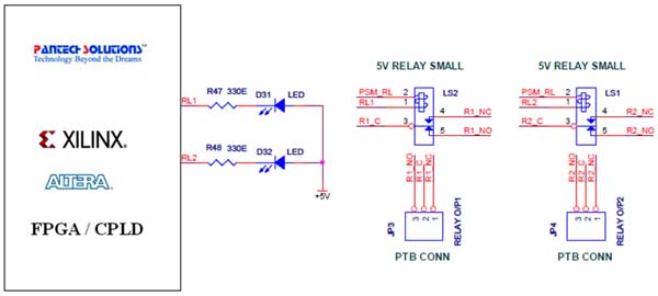
The Universal Development Board features external 5V relay interfacing, as illustrated in the accompanying figure. The ULN2803 is utilized as a driver for FPGA I/O lines, with the driver outputs connected to the relay modules. A PTB connector is...
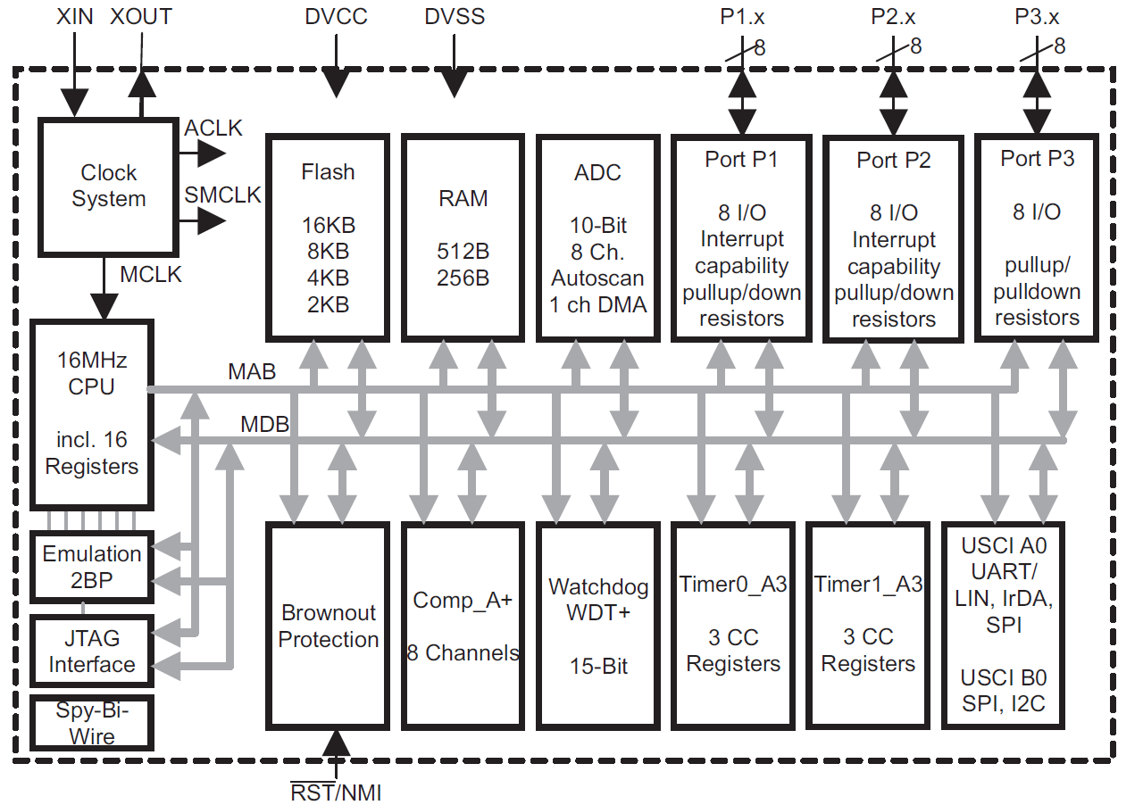
This module provides an overview of the MSP430 microcontroller, instructions on how to read its data sheet, and guidance on selecting the appropriate model for various applications. It is part of a textbook aimed at helping seniors choose Texas...

A prerequisite for this article is that the GCC AVR programming environment is installed as described in the article "Programming the AVR microcontroller with GCC, libc 1.0.4." To avoid installation issues, using the AVR programming CD is recommended. When...
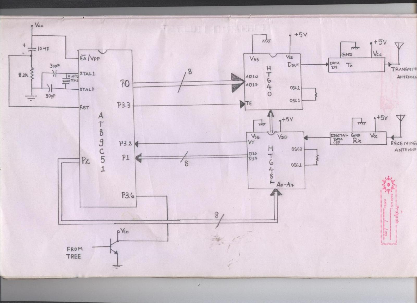
The issue arises when connecting the 8051 microcontroller to the HT640 encoder; the data transmitted is not received by the receiver. However, when the 8051 connections are removed, the transmission functions correctly. This indicates that manual RF communication works...
For beginners in microcontroller projects who are unsure where to start, this project serves as one of the simplest options available. It provides a clear understanding of programming a microcontroller. Often, one may glance at a watch and ponder,...
A device for measuring daily insolation has been developed. The device is constructed using a PIC18F458 microcontroller and a 128MB Multimedia Memory Card (MMC). The insolation measurement device leverages the capabilities of the PIC18F458 microcontroller, which is known for...