
Digital Clock Using Microcontroller 89C52/89S52

This project utilizes a microcontroller, specifically the 89C52, to create a digital clock that displays time in a 24-hour format. The design leverages the capabilities of the microcontroller to manage timekeeping functions and user inputs effectively. The microcontroller is programmed using the Keil compiler, which allows for efficient coding and debugging.
In the schematic, Port 2 is configured as the output port, driving the display components, which may include a 7-segment display or an LCD, depending on the implementation. Port 1 serves as the input port, facilitating user interaction through buttons or switches. The grounding of P1_4 and P1_5 allows the user to toggle between 12-hour and 24-hour formats, providing flexibility in how time is presented.
The use of Proteus software for this project enables simulation and visualization of the circuit before physical implementation. This aids in troubleshooting and refining the design. The digital clock project not only demonstrates basic microcontroller programming but also enhances understanding of input/output operations, timekeeping, and user interface design in embedded systems.
Overall, this project is an excellent starting point for beginners, offering practical experience in microcontroller applications while also providing foundational knowledge applicable to more advanced projects in the future.Are you a beginner in micro controller projects and are you stuck where to start from if yes, then this is one of the simplest mini projects that you can start from. This mini project will give you a clear understanding of programming your micro controller. we sometimes look at our watch and wonder " how does this thing work". Well, in this digita l clock project, you will gain some insight on how micro controller can be used to make it work as a Digital Clock. This project has been done in proteus software. If you are new to proteus software, the tutorials given below may get you started with the software. note:if you are familiar with proteus you can skip this part. The programming of the microcontroller is done using keil compiler. port 2 of 89C52 is used as the output port. whereas port 1 is used as the input port. when P1_4 is grounded the 12 hr mode is activated and when P1_5 is grounded the 24 hr mode is activated.
In the schematic diagram P1_5 is grounded so the 24hr mode is activated. it is as shown below 🔗 External reference
Related Circuits
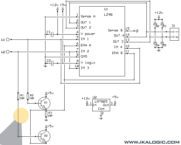
This implementation utilizes the L298 integrated circuit to drive motors and inductive loads with a continuous current capacity of up to 4A. The L298 consists of two independent channels, each capable of driving loads of up to 2A. By...
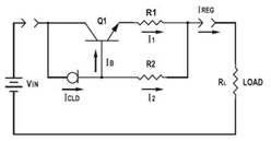
This application datasheet article includes sections that discuss the practical current booster circuit technique, which involves a conventional circuit using a Constant Current Load (CLD) and a current boosting circuit technique. It covers the analysis of the booster circuit...
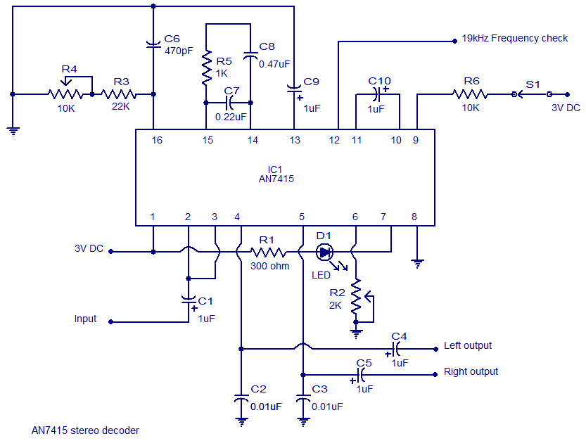
The AN7415 is a monolithic integrated circuit designed for FM stereo demodulation applications. It operates within a voltage range of 1.6 to 7 V DC, making it suitable for handheld FM radios powered by two AA dry cells. This...
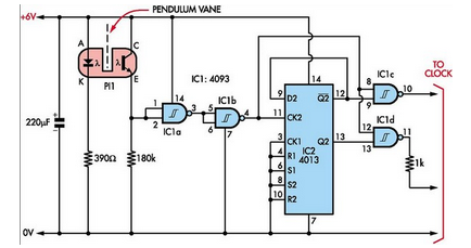
Here is how to build a pendulum-controlled clock that can be made very accurate. Retro? Yes, but it is an interesting project nonetheless. You will need a specific set of components. A pendulum-controlled clock is a mechanical timekeeping device that...
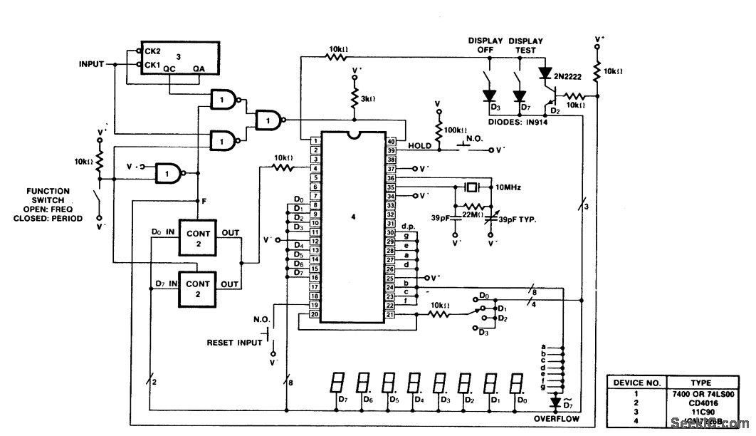
A 100 MHz frequency and period counter is constructed using the Intersil ICM7226B in a 40-pin DIP package. This circuit incorporates a CD4016 analog multiplexer to route the digital outputs back to the function input. The CD4016 operates as...
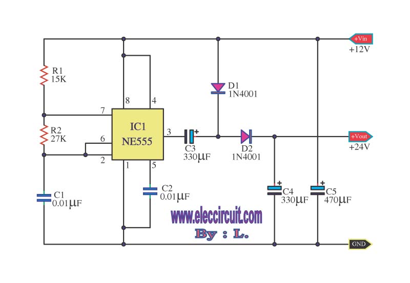
This is a simple voltage doubler circuit that converts 12V DC into 24V DC. It utilizes the popular NE555 timer IC along with a few additional components. The circuit can provide approximately 50mA of current, making it suitable for...