
Introduction
The Universal Encoder/Decoder, or Uncoder, is designed to enhance the functionality of older 2-Meter FM transceivers by integrating a tone encoder and decoder that automatically detects and remembers CTCSS tones. This device addresses the limitations of traditional tone encoders, which require manual adjustments and prior knowledge of repeater tones. The Uncoder's design focuses on user convenience and safety, allowing operators to change frequencies without distraction.
The core of the Uncoder is the ATmega8 microcontroller, which provides the necessary computational resources and flexibility for the project. Its architecture includes a robust set of features that streamline the design process. The microcontroller's 8K program flash is utilized for storing the device's firmware, while the 512 bytes of EEPROM are allocated for maintaining a list of CTCSS tones associated with various frequencies. The RAM further supports temporary data storage during operation.
The frequency detection mechanism is a critical component of the Uncoder. The input capture feature of the ATmega8 microcontroller allows it to accurately measure the frequency of incoming signals. This is achieved by capturing the value of an internal counter at the moment a transition is detected on the input capture pin. This capability effectively replaces the need for a separate frequency counter, simplifying the overall design.
The RF signal from the transceiver's local oscillator is fed into the Uncoder, where it is processed by the LMX1501 Frequency Synthesizer. This chip not only amplifies the incoming signal but also divides it down to a manageable frequency for further analysis. The output from the LMX1501 is then utilized by the microcontroller to determine the appropriate CTCSS tone for the current operating frequency.
In summary, the Uncoder represents a significant advancement in the usability of older 2-Meter FM transceivers. By incorporating modern technology and user-friendly features, it allows for seamless operation across multiple repeaters without the need for manual adjustments, thus enhancing both convenience and safety for the operator.What do you do with those old 2-Meter FM rigs that don`t have any CTCSS tone capability Well, you add it of course! While big knob` tone encoders have been available from several sources, their downside has been having to know the tone of the repeater you would like to use and the need to turn the knob every time you change repeaters.
Wouldn`t it be nice to have an add-on tone encoder, and decoder, that sniffs the PL from the repeater just like those fancy new rigs Plus as an added convenience, and safety feature, remember what the tone was for each repeater! Imagine, not having to take your eyes off the road to rotate a knob just to change the PL! Now you can have all this and, as the man on the late night infomercials says, more with the Uncoder!
The details of a Universal Encoder/Decoder, or Uncoder for short, really started to gel when I decided to resurrect a couple of 2 meter rigs that had been laying around the shop, unused, for quite a while. One of the rigs was a Kenwood TS-700A all-mode base station transceiver and the other was a TR-7400A mobile that I wanted to be able to use with some of the local PL required repeaters.
I wanted a device that was intuitive to use; just tune the transceiver to the repeater and let the Uncoder worry about the tone setup. The best solution would be a tone encoder / decoder that could detect the frequency that I was operating on and set the tone frequencies appropriately.
Once I had given the Uncoder the CTCSS tone information for a particular frequency, it should be able to remember the setting and automatically set up the tone info as I tuned my radio to various repeaters. To accomplish this task, the Uncoder needed to incorporate a frequency counter, along with the tone encoding / decoding and the appropriate microcontroller circuitry.
The selection of a microcontroller chip to base a design on is an important decision in working out a circuit. The microcontroller needs to have enough memory, I/O pins, and system resources to support the work it needs to perform.
Although there are many fine microcontroller products available in the market, I have always been a fan of Atmels` line of flash programmable devices. One great feature of many of the processors in Atmels` line of microcontrollers is the ability to serially program the flash code memory space in the chip while it is installed in the circuit.
With this feature you can make changes in the program and then download the new code to the microcontroller without removing or changing any of the components on the circuit board. This is a great advantage while debugging your code. The device I chose for this project was the ATmega8 microcontroller. The Atmega8 incorporates 8K of program flash, 512 bytes of EEPROM, to hold the frequency tone lists, 1K of RAM, several internal counter / timers with input capture facilities as well as serial pots and even an 8 channel A/D converter.
Although I didn`t use all of the Atmega8s features, some really help simplify the design of the Uncoder. The ATmega8s input capture feature, along with its associated timer, allows the microcontroller to accurately measure the period of a waveform.
An input transition on the Input Capture Pin, U2 pin 12, causes the microcontroller to record the value one of its internal counters which is being continuously incremented by the processors crystal controlled clock. This action performs most of the functions of the frequency counter portion of the Uncoder. RF, generated by the transceiver local oscillator, is brought into the Uncoder at spring pin P1. The local oscillator signal is coupled to the input, pin 8, of IC U7 a LMX1501 Frequency Synthesizer chip.
Although the LMX1501 is intended to be used as a frequency generation device in the Uncoder U7 is used to amplify the local oscillator and divide the frequency down to a point where its perio 🔗 External reference
Related Circuits
With the increasing awareness of environmental issues and the energy crisis, the development and utilization of new energy sources have garnered more attention. Solar energy has recently become popular due to its inexhaustible, efficient, and pollution-free characteristics. The photovoltaic...

The schematic closely resembles the one found in the CPLD Development Board Tutorial, as it is essentially the same board with a minor addition. The new components are located in the lower right corner, including eight DIP switches, a...
The inverter is a device that converts direct current (DC) from a battery or storage battery into alternating current (AC), typically at 220 volts and 50 Hz, producing either sine waves or rectangular waves. It serves as a common...
KGA8010 is a broadband distributed amplifier utilizing 0.1 um-gate GaAs P-HEMT and coplanar waveguide technologies. The KGA8010 can serve as a multi-purpose amplifier for 40 Gb/s optical communication and millimeter wave applications. Manufactured by Oki Semiconductor. The KGA8010 broadband distributed...
This two-part article explains the utilization of a simple voltage divider circuit incorporating a thermistor to obtain high-accuracy temperature readings across a wide range of measurements. The first part focuses on the circuit design and explores various methods for...
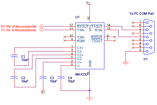
Serial communication using UART or USART of a microcontroller 8051 AVR PIC, software implementation of half-duplex UART and MAX232 interfacing with microcontrollers 8051 AVR PIC. The described system focuses on implementing serial communication via UART (Universal Asynchronous Receiver-Transmitter) or USART...