
Thermistors As Accurate Temperature Sensors Part 1: Introduction and Methods

The voltage divider circuit is a fundamental electronic configuration that allows for the measurement of voltage levels in relation to a reference voltage. In this application, the thermistor, a temperature-sensitive resistor, is used to provide a variable resistance that changes with temperature fluctuations. The circuit typically consists of two resistors arranged in series, with the thermistor acting as one of these resistors.
When a voltage is applied across the series combination, the output voltage can be taken from the junction between the two resistors. This output voltage varies as the resistance of the thermistor changes with temperature, allowing for the calculation of the temperature based on the output voltage. The accuracy of the temperature readings can be enhanced by employing calibration techniques and compensating for non-linear characteristics of the thermistor.
Various temperature estimation methods can be implemented with this setup, including linear approximation, polynomial fitting, and look-up tables, which can improve the precision of the readings over the desired temperature range. The implementation of filtering techniques may also be beneficial to minimize noise and improve the stability of the measurements.
In summary, the combination of a voltage divider circuit and a thermistor provides an effective means for achieving accurate temperature measurements, making it suitable for a variety of applications in electronics and environmental monitoring.This two-part article describes how to use a simple voltage divider circuit with a thermistor to achieve high-accuracy temperature readings over broad measurement ranges. Part one discusses the circuit and various temperature estimation methods.. 🔗 External reference
Related Circuits

This temperature meter utilizes the precision micro power centigrade sensor IC LM35. The output voltage of the IC is linearly proportional to 10 mV per degree centigrade. The LM35 temperature sensor is a versatile and widely used device in electronic...
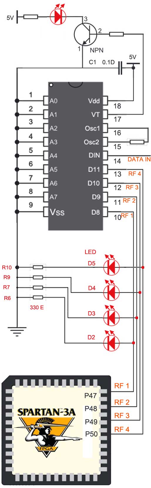
The RF module operates at radio frequencies, with a frequency range between 30 kHz and 300 GHz. In this RF system, digital data is represented as variations in the amplitude of a carrier wave, a modulation technique known as...
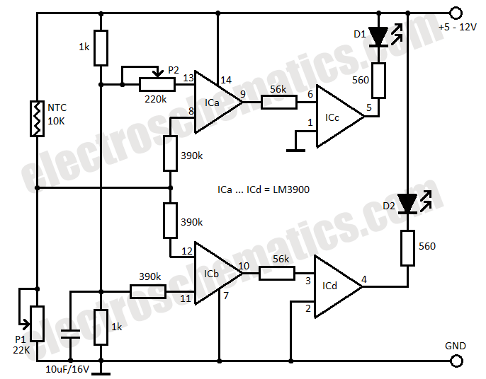
This temperature monitor alarm circuit continuously monitors room temperature and emits a beep when the temperature falls below 20 degrees Celsius. The ability to constantly check the temperature can help reduce air conditioning costs by reminding users to turn...
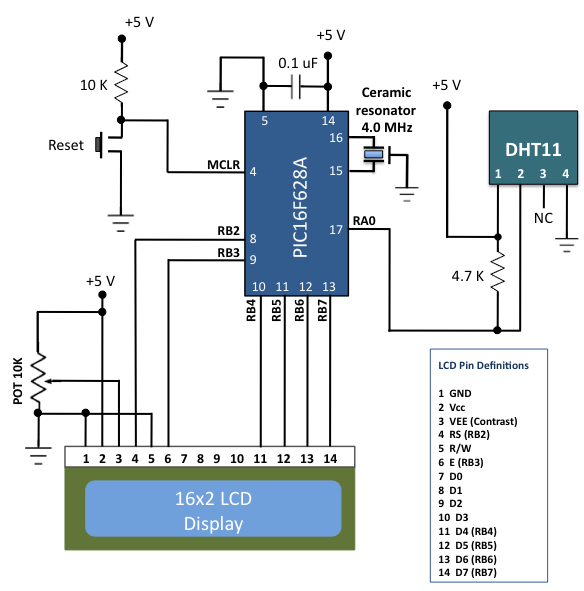
The DHT11 is the most affordable sensor currently available in the market that provides calibrated digital outputs for temperature and relative humidity. The DHT11 sensor is a low-cost digital sensor that measures both temperature and relative humidity. It operates...
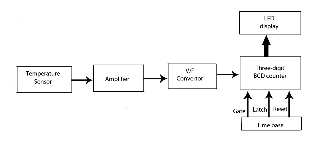
This verified project provides an idea, circuit, and operation of the LED display temperature indicator. It features a digital temperature indicator utilizing a voltage-to-frequency (V/F) converter, along with various electronic projects. The LED display temperature indicator is designed to provide a...
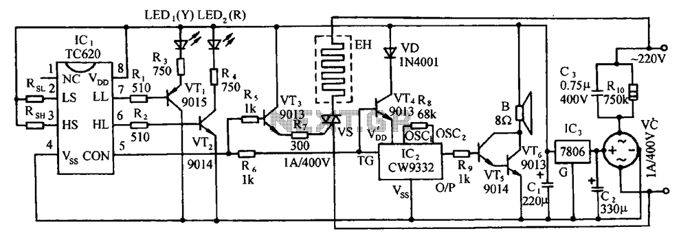
The circuit includes the TC620 temperature control circuit, the temperature indicator circuit, a thyristor-controlled heating circuit, a vocal music buck rectifier circuit, and the AC circuit. The TC620 temperature control circuit is designed to regulate temperature by monitoring the temperature...