
inverter 12v dc to 240v dc circuit

The inverter circuit operates by converting the DC voltage from the car battery into an AC voltage suitable for powering various devices. The 555 timer, functioning as an astable multivibrator, generates a square wave signal with a frequency that can be adjusted by altering the resistors and capacitors in the circuit. This flexibility allows the inverter to be tailored for specific applications, ensuring optimal performance.
Transistors T1 and T2 are crucial components in this design, acting as switches that control the flow of current through the transformer. When T1 is activated, it allows current to pass through one half of the primary winding, generating a magnetic field in the transformer. As the magnetic field collapses, T2 is activated, allowing current to flow through the other half of the primary winding. This alternating action creates the necessary magnetic field changes to induce a high voltage in the secondary winding of the transformer.
The use of Zener diodes D4 and D5 is essential for protecting the transistors from voltage spikes that can occur during the switching process. These diodes clamp the voltage, preventing damage to the transistors and ensuring reliable operation of the inverter circuit.
The output voltage from the secondary winding can be utilized directly for AC-powered devices or can be rectified using additional components, such as diodes and capacitors, to provide a stable DC output. This versatility makes the inverter suitable for a wide range of applications, from powering small household appliances to specialized equipment in various fields. Overall, the design presents a robust solution for converting low-voltage DC into high-voltage AC, with adjustable frequency capabilities to meet diverse needs.This inverter circuit can be used to power electric razors, stroboscopes and flash tubes, and small fluorescent lamps from a 12 volt car battery. In contrast to the usual feedback oscillator type of inverter, the oscillator of this inverter is separate from the output stage, which allows easy adjustment of the oscillator frequency to suit differen
t applications. The oscillator circuit consists of a 555 timer connected as an astable multivibrator. The inclusion of D1 ensures that the duty-cycle of the squarewave output is maintained at about 50%. The output of the 555 drives the base of T1 which switches current through one half of the primary of the transformer. T2 is driven from the collector of Tl and thus switches current through the other half of the transformer winding on opposite half cycles of the drive waveform.
Zener diodes D4 and D5 protect Tl and T2 from any high-voltage spikes generated by the transformer. The voltage applied to the transformer primary is stepped up and the required high output voltage appears across the secondary winding. Depending on the application the secondary voltage may or may not be rectified. 🔗 External reference
Related Circuits
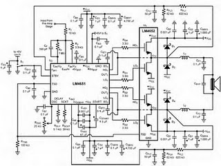
The following circuit illustrates the LM4652 integrated circuit used in a 170 Watt power amplifier configuration. It is commonly utilized in portable HiFi systems. The LM4652 is a high-performance audio amplifier IC designed to deliver substantial power output while maintaining...

A simple touch dimmer circuit diagram using the TT6061 IC, which is a touch control integrated circuit used for light dimmer circuits and lamp dimmer circuits. The touch dimmer circuit utilizing the TT6061 IC is designed to provide a user-friendly...
The CDI ignition circuit generates a spark from an ignition coil by discharging a capacitor across the primary winding of the coil. A 2µF capacitor is charged to approximately 340 volts, with the discharge process controlled by a silicon-controlled...
A simple square wave oscillator can be created using two gates from a CMOS 4011 NAND chip. Alternatively, a CMOS 4001 chip or a TTL equivalent can also be utilized. In this circuit, the mark-space ratio can be independently...

The output displays a 5V / 0.4A low-power switching power supply circuit, which can be utilized to create a transformer saturation soft-switching circuit. This low-power switching power supply circuit is designed to provide a stable 5V output at a current...
This circuit is a compact +5V power supply that is beneficial for digital electronics experimentation. Inexpensive wall transformers with variable output voltage can be found at electronics shops and supermarkets. While these transformers are readily available, their voltage regulation...
Warning: include(partials/cookie-banner.php): Failed to open stream: Permission denied in /var/www/html/nextgr/view-circuit.php on line 713
Warning: include(): Failed opening 'partials/cookie-banner.php' for inclusion (include_path='.:/usr/share/php') in /var/www/html/nextgr/view-circuit.php on line 713