
square wave oscillator circuit
The circuit design for the square wave oscillator employs two NAND gates configured in a feedback loop. The first NAND gate is used to generate a basic pulse signal, while the second NAND gate provides feedback to establish oscillation. The configuration allows for the adjustment of the mark-space ratio by changing the resistor values connected to the gates.
In this configuration, the resistors are connected to the inputs of the NAND gates, influencing the timing characteristics of the output waveform. The timing components determine how long the output remains high versus low, effectively controlling the frequency of the oscillation.
The performance of the oscillator is influenced by the supply voltage applied to the IC. Higher voltages generally lead to faster rise and fall times, which can be critical for applications requiring precise timing. The choice of IC also impacts the output characteristics; for instance, CMOS devices typically have lower power consumption compared to their TTL counterparts, making them suitable for battery-operated applications.
When designing the circuit, it is essential to consider the load connected to the output. The output stage of the NAND gates can drive a variety of loads, but excessive loading may affect the rise and fall times. Proper decoupling capacitors should be included near the power supply pins of the IC to enhance stability and reduce noise.
In summary, this simple square wave oscillator circuit utilizing CMOS NAND gates provides flexibility in frequency generation and offers the ability to control the mark-space ratio through resistor adjustments. The circuit is suitable for various applications, including clock generation, signal modulation, and waveform shaping.Using two gates from a CMOS 4011 NAND chip, a simple Squarewave oscillator can br made. Alternatively a CMOS 4001 chip can also be used, or a TTL equivalent. In this circuit the mark space ratio can also be independently controlled by varying the value of the resistors. The rise and fall times of the output pulses depend on the operating voltage o f the IC and type of IC, but will be typically in the order on tens of nanoseconds. 🔗 External reference
Related Circuits
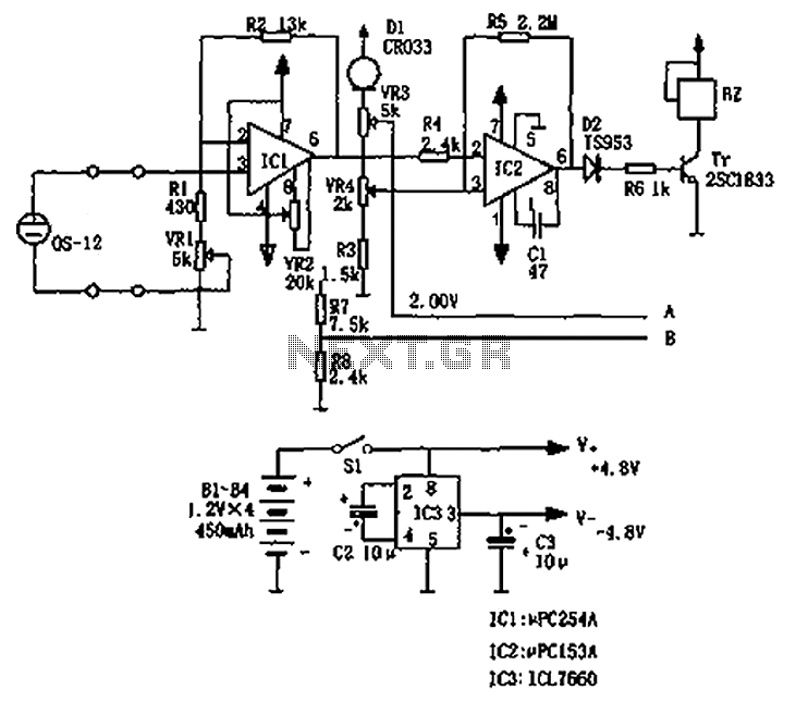
The circuit principle involves an oxygen sensor circuit utilizing the OS-12, a DC amplifier IC1, an A/D converter IC4, a liquid crystal display F2100-34PI, a voltage comparator IC2, and a positive and negative power converter IC, among other components....
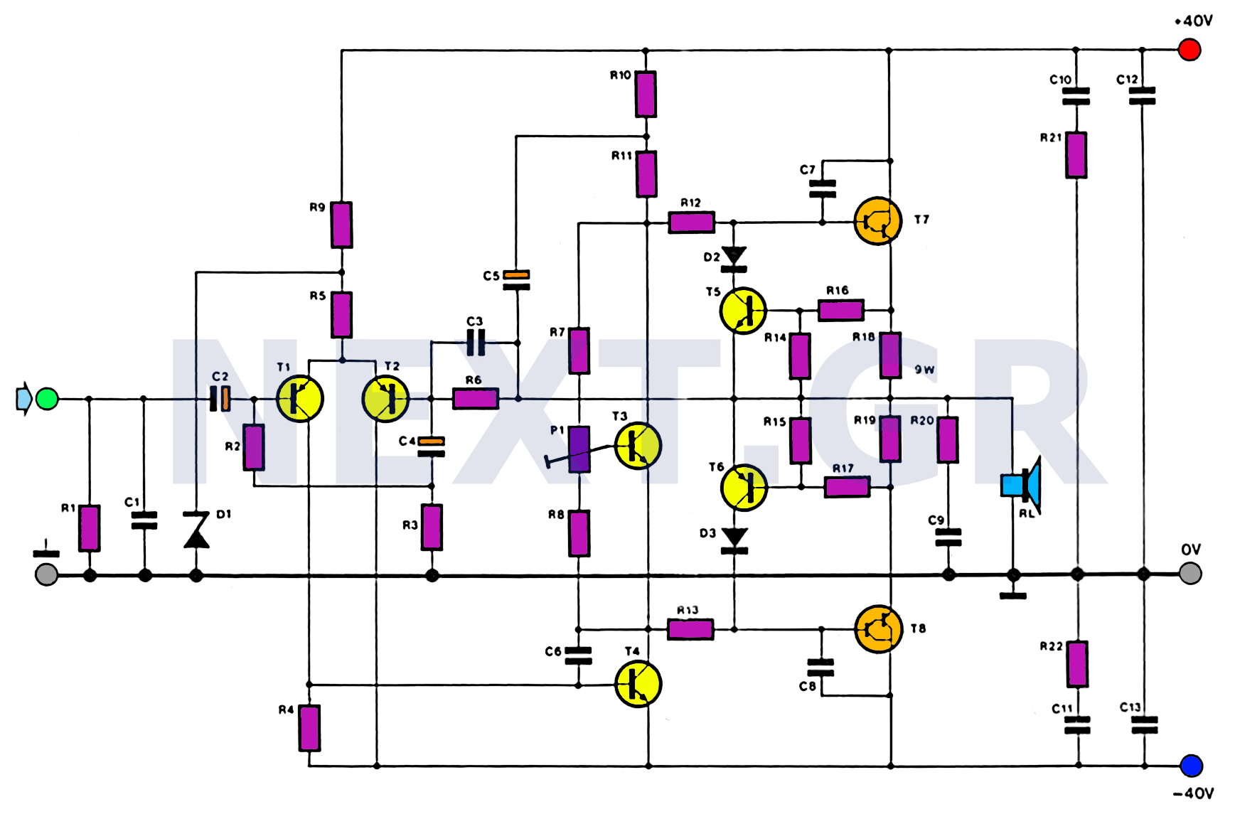
This amplifier is designed with the following specifications: distortion less than 0.1% at full power of 100W even at 20KHz, with power attributed to an extended bandwidth. The output transistors are protected against short circuits, and the power supply...
This broadband AM receiver allows monitoring of the shortwave radio band. The circuit is intentionally designed for low selectivity and exhibits maximum sensitivity in the frequency range of 6 to 20 MHz, which encompasses most shortwave broadcast stations. In...
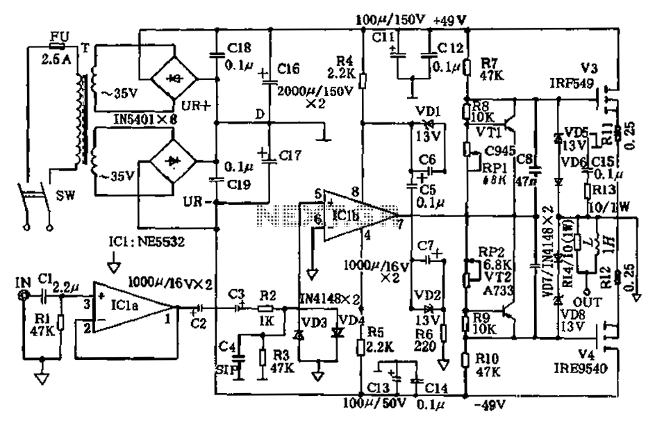
The amplifier circuit presented in this paper introduces a floating power supply aimed at increasing output power. The output power of the amplifier is influenced primarily by the final stage amplifier supply voltage. The circuit's principle is illustrated in...
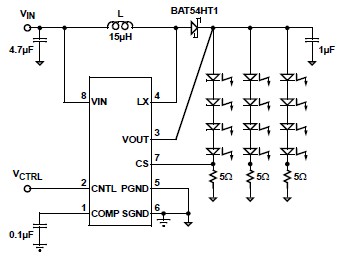
A simple white LED driver schematic can be created using the EL7513 constant current boost regulator, which is specifically designed for driving white LEDs. This driver can manage 4 LEDs in series or up to 12 LEDs in a...

This device enables two computers to share a single USB printer or other USB devices, including external flash drives, memory card readers, or scanners. A rotary switch is used to select the PC that will access the USB device, while...