
inverter circuits
Inverter circuits are essential components in various applications, converting direct current (DC) into alternating current (AC). The typical frequency of operation for these circuits is between 50 Hz and 60 Hz, which aligns with standard power supply frequencies used in many regions worldwide. The inverter circuits discussed are designed to handle loads up to two amps, making them suitable for low to moderate power applications.
The design of these inverters typically involves a few critical components: a DC power source, oscillators, switching devices (such as transistors or MOSFETs), and a transformer. The oscillator generates a square wave signal at the desired frequency. This square wave is then used to turn the switching devices on and off, creating an alternating current output. The transformer steps up or steps down the voltage as needed while isolating the load from the DC source.
Protection mechanisms are often integrated into inverter designs to prevent overheating and overcurrent conditions. When the load exceeds the two-amp threshold, the inverter automatically shuts off to protect the circuit from damage. This feature is crucial for maintaining the reliability and longevity of the inverter.
Inverter circuits can be applied in various scenarios, including powering small household appliances, charging batteries, and providing emergency backup power. Understanding the specifications and limitations of these circuits allows for effective integration into electronic systems, ensuring optimal performance and safety.Some good inverter circuits I fond they, oscillate at about 50 to 60Hz. They will probably handle up to about two amps any more and the will auto shut off. Have questions ask me leave your questions in the comment box or email me at ericgoodchild@yahoo. com 🔗 External reference
Related Circuits
AN79 Linear Technology AN79 modifies methods presented in AN74, allowing for the verification of 30 nanosecond amplifier settling times with 0.1% resolution. The sampling-based technique used is detailed, and results are presented. Appendices cover oscilloscope overdrive issues, the construction...
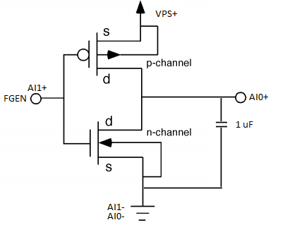
The DC to AC inverter circuit illustrated in the schematic is a straightforward design that produces a square wave output, which is sufficient to power various devices. The schematic diagram of the inverter circuit features a MOSFET configured as...
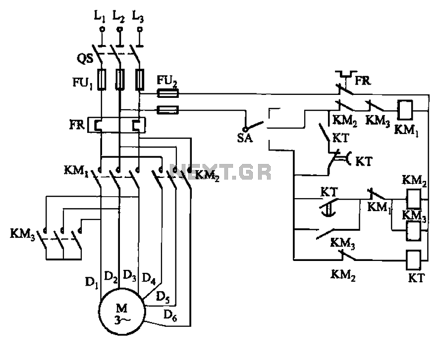
The circuit depicted in Figure 3-98 demonstrates how motor starting and low-speed operation are managed using switch SA. By adjusting the time relay KT, the motor's operation can transition from low speed to high-speed operation within a specified time...
Dark Activated Switch or Porch Light Switch. This circuit activates a relay when the light level drops below a preset threshold. The light sensitivity can be adjusted using variable resistor VR1, and the relay contacts can control an external...
Using measured threshold voltage and Ids-Vds curves, the performance of first-order MOSFET theory can be evaluated in real devices, allowing for an understanding of the limitations of first-order theoretical MOSFET equations. The MOSFETs employed in this experiment are from...
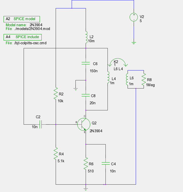
The previous tutorials on SPICE simulation in Fedora Electronic Lab have introduced various concepts. This post focuses on Part 3, assuming familiarity with gschem and completion of a course on analog electronic circuits. It is advised to review the...