
Simulating Circuits
This tutorial presents a structured approach to simulating a BJT amplifier circuit using ngspice within the Fedora Electronic Lab environment. The user is expected to have a foundational understanding of analog electronic circuits and familiarity with gschem, the graphical schematic editor used in conjunction with ngspice.
To begin, the user should set up a directory structure to organize the project files effectively. The necessary transistor models can be sourced from Fairchild Semiconductors, while diode models are available from Diodes.com, ensuring compliance with copyright restrictions by not including them directly in the tutorial.
The simulation process starts with generating the netlist from the schematic, where the input and output nodes must be clearly identified. A command file (.cmd) is created to instruct ngspice to perform an AC analysis. The command should specify a frequency sweep from 1Hz to 1MHz, with a logarithmic scale and 10 points per decade for detailed analysis. The command syntax would typically look like this:
```
.ac dec 10 1Hz 1MHz
```
After running the simulation, the output voltage at the collector of the BJT amplifier can be plotted using gwave, with the X-axis set to a logarithmic scale for better visualization of the frequency response.
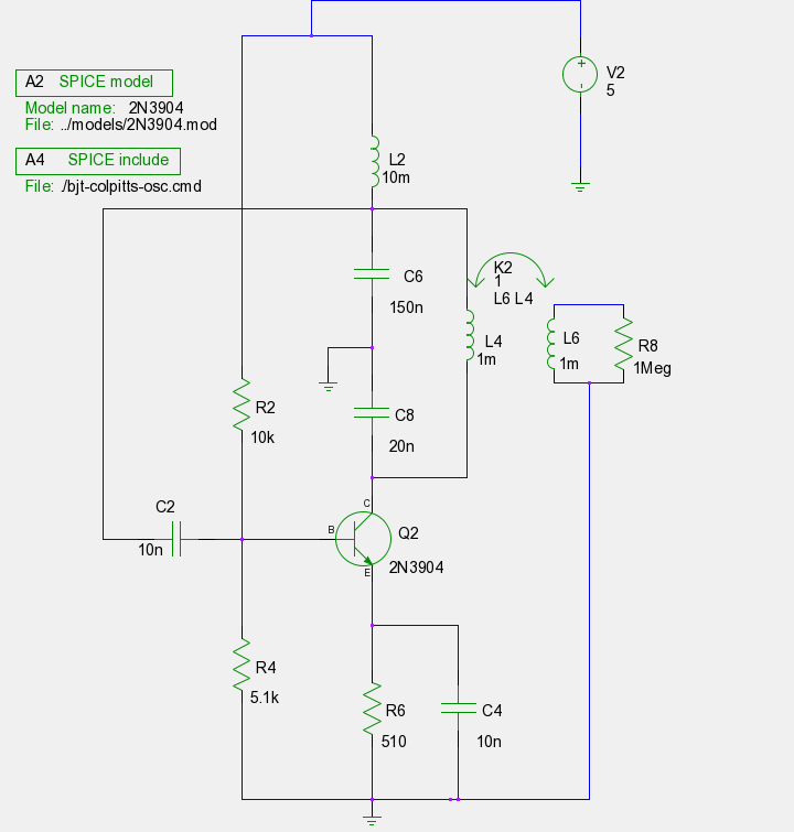
The tutorial also addresses the inclusion of inductors in the circuit. Inductors can be found in the same section as resistors and capacitors within the schematic editor. The user is guided to set the inductance value appropriately. For mutual inductance, the tutorial instructs the user to select the appropriate SPICE simulation element and configure its attributes as needed.
The overall goal of this tutorial is to enhance the user's proficiency with SPICE simulations in the Fedora Electronic Lab, encouraging experimentation with subcircuits (SUBCKTS) to modularize complex designs. Feedback and questions from the user community are welcomed, fostering an interactive learning environment.Hope you liked my previous tutorials on SPICE simulation in Fedora Electronic Lab. Well this post comes a little late because I had a lot of circuits in mind. So take a deep breadth and get ready for Part 3! :) I`m assuming that you`ve read through the previous two tutorials and that you are now comfortable with using gschem. After this tutorial, you must go through the ngspice manual atleast once. I`ll be moving a bit fast from now on because there is a lot to cover. If something is not clear, feel free to post a comment. I also assume that you`ve completed a course on analog electronic circuits. If you are currently in such a course, go through the circuits you are familiar with and come back later. Remember to plan a directory structure before each example. Also, the models for the transistors are available from Fairchild Semiconductors and diodes from Diodes.
com. I`m not posting these here due to copyright restrictions. Get the netlist and simulate. Open the netlist and see which nodes are the input and output nodes. Run gwave and plot these nodes. This is what you should get: Simple as always. Lets move on. From now on I will tell you the circuit attributes only for components we haven`t seen yet. You can figure out the rest easily by seeing the schematic. I`m sure you can keep up :) The circuit doesn`t contain a capacitive filter however. Use the same. cmd file as the halfwave rectifier. Generate the netlist and run the simulation. Now run gwave. This time plot only the ouput node. The input is a difference of two nodes and this is not available on the list. (If some one knows how to get this in batch mode please post a comment). This is the output: We`ll look at a simple BJT (bi-polar junction transistor) amplifier now. This time we`ll see the AC response, i. e. the output of the amplifier over a range of input frequencies (sinusoidal input). Here is the circuit: We need to add the word AC before it to tell ngspice that we will be using this source for the AC analysis. The rest of the circuit is straightforward. Use the following line in your cmd file: This tells ngspice that we want to perform an AC analysis, we need a decade frequency variation from 1Hz to 1MHz with 10 points per decade.
Again, read the manual for more info. Generate the netlist, run the simulation and plot the voltage variation at the ouput node i. e. at R10. In gwave, go to Options > X Axis Scale > Log. This is what the output should look like: Nothing really new in this circuit. I`ve used a different transistor this time. The model for this is also available at Fairchild`s website. Once you`re done constructing the circuit, use the following cmd file: You know what to do, get the netlist then simulate and run gwave. Plot the output i. e. the voltage at the collector of the transistor. Hope you got this one right too. Two new things to learn here. Lets check out the schematic first. Draw the circuit first and give values to the components you are familiar (i. e. everything except the inductors). Okay. Inductors are pretty straightforward. You`ll find inductors in the same section as the resistors, capacitors and transistors. Just set an inductor`s value attribute: Now for the mutual inductance. You`ll find this one in the SPICE Simulation Elements section. Select and place kmutual-1. sym (where you place it doesn`t matter) on the schematic. Double click it. You`ll see the attributes you need on the table already. Here are the settings: Whew! That was a long one! Well I`m sure that after this, you should be a lot more comfortable with SPICE in FEL. Go over this again slowly. Next, we will look at sub circuits (SUBCKTS) which allow us to use op-amps, or even break our circuits into more fundamental modules.
Till then try some other circuits on your own and do post a comment if you have any questions. Finally, any feedback is appreciated. Hope you liked this tutorial and I hope this helps. Thanks for reading! :) 🔗 External reference
Related Circuits
In 2011, designing a frequency converter circuit typically involves selecting an integrated circuit (IC) that meets specific requirements regarding gain and mixer spurious products, along with adding a couple of filters and a power supply. Often, the oscillator is...
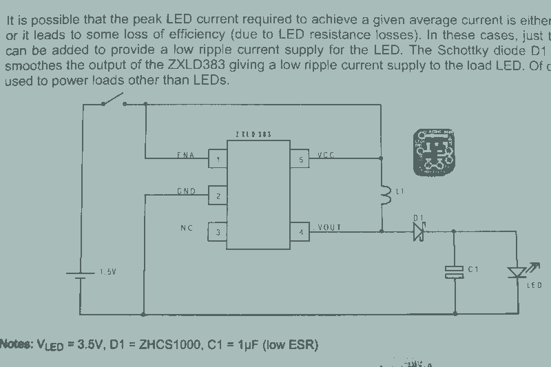
It may seem that due to the numerous flashlight projects undertaken, there is a significant collection of lights. The inductor can be altered to set the current level, but the total current fluctuates with the battery supply, decreasing as...
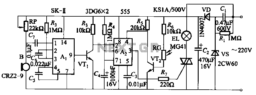
This circuit utilizes a dedicated voice integrated circuit (AI) of the SK type, which incorporates an internal bistable multivibrator and three inverting amplifiers. The 555 integrated circuit (IC) A2 is employed for delay control. The described circuit is designed to...
This application note explains how the transfer function of most operational amplifier circuits can be derived through a straightforward process of nodal analysis. The transfer function of operational amplifier (op amp) circuits is a critical aspect for understanding their behavior...
Over 1400 top electronics projects and electronic circuits with photos, datasheets, and easy-to-read schematics, along with explanations of how they work and how to build them. The collection comprises a vast array of electronics projects suitable for enthusiasts and professionals...
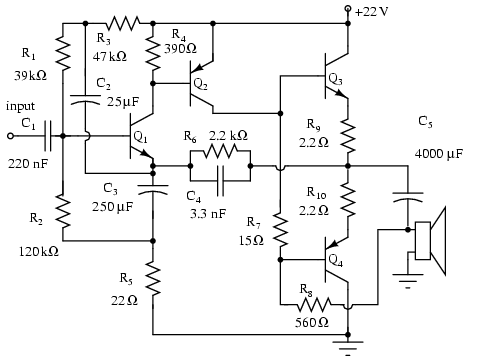
Note that Q3 and Q4 in the figure below are complementary, with Q3 being an NPN transistor and Q4 being a PNP transistor. This circuit is suitable for moderate power audio amplifiers. For a detailed explanation of this circuit,...