
Invisible Infrared Alarm Circuit
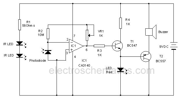
The infrared movement detection circuit employs an infrared LED and a photodiode or phototransistor as its primary components. The infrared LED emits light that is not visible to the human eye, creating an invisible beam across the doorway. When a person passes through this beam, the emitted infrared light is reflected or blocked, causing a change in the light intensity detected by the photodiode or phototransistor.
The circuit is typically powered by a low-voltage DC source, such as a battery or a DC power supply. The infrared LED is connected in series with a current-limiting resistor to prevent it from drawing excessive current, while the photodiode or phototransistor is connected in a configuration that allows it to respond to the changes in light intensity.
Upon detecting the interruption of the infrared beam, the photodiode or phototransistor triggers a microcontroller or a simple comparator circuit. This component processes the signal and activates a sound-generating device, such as a buzzer or speaker, producing a short beep to alert when motion is detected.
For optimal performance, the circuit may include additional features such as adjustable sensitivity, delay timers, or indicators to enhance functionality. The placement of the infrared LED and photodiode or phototransistor is crucial; they must be aligned correctly to ensure the integrity of the infrared beam across the doorway. Proper housing and positioning can also mitigate false triggers from ambient light sources.This circuit uses invisible infrared light to detect the movement of people through the door. A short beep will be generated when the infrared beam breaks 🔗 External reference
Related Circuits

IC1-c functions as a non-inverting comparator, while IC1-a operates as an inverting comparator. Potentiometer R1 and fixed resistors R2 and R3 create a voltage divider chain that provides slightly different voltages to the two comparators. These voltages establish the...
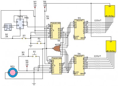
This is a 24-second countdown timer circuit designed for automatic control of electronic loads. The timer circuit utilizes fast 74LS Schottky integrated circuits (ICs). A 24-second countdown begins when switch S3 is off and switch S2 is pressed. Switch...

This document presents the circuit diagram of a simple three-band graphic equalizer that utilizes a single integrated circuit (IC) and a few additional components. The IC employed in this design is the LF351, which is a wide bandwidth single...
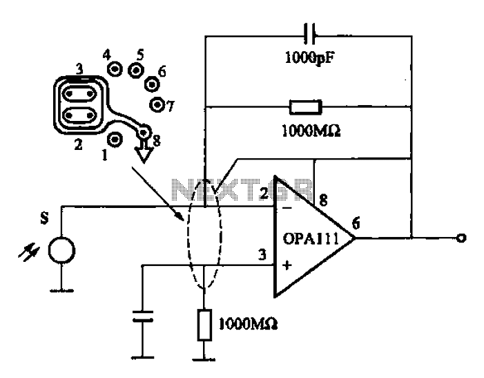
Infrared heat is emitted by an object during non-contact temperature measurement. The measured signal is weak, necessitating the use of highly sensitive thermal infrared sensors with minimal noise. Consequently, the amplifier circuit must also meet stringent requirements, as standard...

This design circuit is for audio graphic equalizers, which are commonly found as commercial products, yet published circuits for them are quite rare. The circuit features a simple design that requires an operational amplifier (op-amp) to amplify the input...
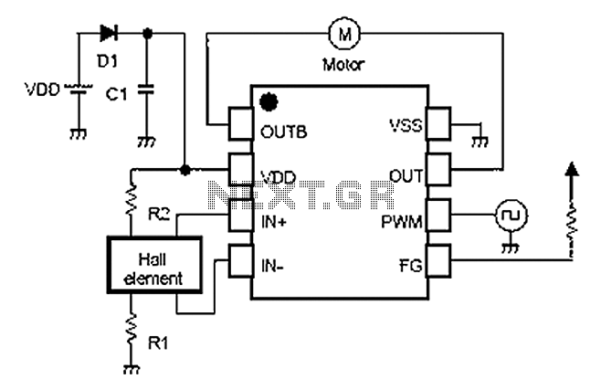
A simple single-phase brushless DC motor drive using the NJU7365 motor driver IC from New Japan Radio Co., Ltd. The NJU7365 is designed for single-phase motor applications and features built-in MOSFET motor drives, direct PWM input, FG output, and...