
IR Remote Control Tester

This circuit comprises several key components: the TSOP1738 IR receiver, a piezo buzzer, a voltage regulator, and passive components such as resistors and capacitors. The TSOP1738 is sensitive to IR signals modulated at a frequency of around 38 kHz, which is typical for most remote controls. When the remote control is activated, it emits IR pulses that the TSOP1738 receives. The IC demodulates these signals, outputting a square wave at a frequency of approximately 700 Hz, which corresponds to the modulation of the incoming IR signal.
The piezo buzzer is directly connected to the output of the TSOP1738. When the output from the TSOP1738 goes high, it energizes the piezo buzzer, causing it to produce sound. This audible indication allows users to easily determine if the remote control is functioning properly without the need for additional equipment.
The power supply circuit is designed to convert the 9V from the PP3 battery down to a stable 5V required by the TSOP1738 and the piezo buzzer. This is typically achieved using a linear voltage regulator, which ensures that the circuit operates reliably across various battery conditions.
Overall, this circuit serves as an efficient and effective tool for testing the operation of infrared remote controls, offering portability and ease of use while providing clear audio feedback on the status of the remote control's IR signal.This small circuit is ideal for checking the basic operation of an infrared remote control unit. The circuit is based on the brilliantly simple idea of connecting a piezo buzzer directly to an IR receiver IC. This method is almost as simple as connecting a photodiode directly to the input of an oscilloscope, but has the advantage that no oscillosc
ope is needed: the compact unit is always ready to use and much easier to carry around than bulky test equipment. Operation of the remote control is indicated by the buzzer making a chattering noise. The circuit is very sensitive and has a range of several meters. The TSOP1738 integrated IR receiver accepts, amplifies and demodulates the IR signal from the remote control, producing an output with a frequency of around 700 Hz.
The piezo buzzer is connected to its output, rendering the signal audible. All the other components are simply concerned with producing a stable 5 V power supply from the 9V PP3-(6F22) type battery. Instead of the TSOP1738 similar devices from other manufacturers can be used, and of course carrier frequencies other than 38 kHz can be used.
The circuit still works if there is a mismatch between the nominal carrier frequencies of the transmitter and receiver IC, but range is reduced. It is still, however, adequate for determining whether a remote control is producing an IR signal or not.
🔗 External reference
Related Circuits
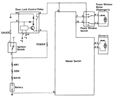
The following circuit illustrates the 1993 Toyota Hilux Pickup Power Window Control System Electrical Circuit Diagram. It is beneficial for both personal use and for mechanics during repairs. Key components include the door lock relay, junction block, power window...
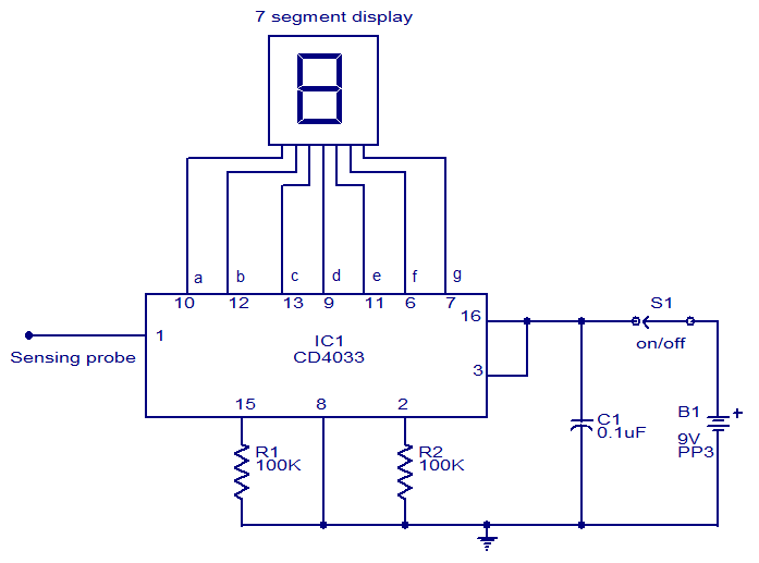
This circuit is designed to test the presence of mains voltage without direct electrical contact with the mains line. The core component of this circuit is the CMOS IC CD4033, which features a five-stage decade Johnson counter and an...
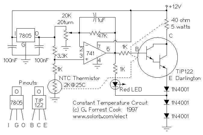
This circuit was built to stabilize a radio frequency VFO (Variable Frequency Oscillator) for ham radio applications. The circuit has also been used to lower the drift of a Ramsey FM10a micropower FM transmitter. More: The 7805 voltage regulator...
Short circuits or broken PCB tracks can be easily identified using a multimeter. However, this tool may yield inaccurate results when assessing the efficiency of a transistor or diode unless the component is unsoldered and removed from the PCB....
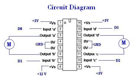
A remote Sun SPOT will transmit data to a Sun SPOT mounted on a car, which will control an integrated circuit (IC) according to the digital input/output pins D0 to D3. The IC will subsequently drive the motors that...

A bidirectional H-bridge DC motor control circuit is illustrated. The circuit utilizes the L298 integrated circuit from ST Microelectronics. The L298 is a dual full-bridge driver that supports a wide operating voltage range and can manage load currents up...