
Wireless mains voltage tester
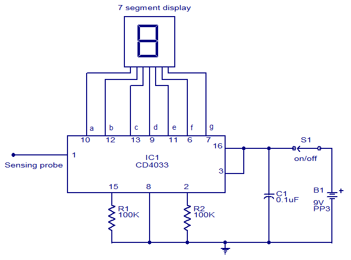
The circuit employs the CD4033 CMOS IC, which is known for its low power consumption and high noise immunity, making it ideal for applications involving sensitive detection of voltage. The five-stage Johnson counter within the IC allows for counting up to ten, which is displayed on a standard seven-segment LED display. The sensor wire acts as an antenna, picking up electromagnetic signals from the nearby mains line. The length and insulation of the wire are critical; however, the description mentions it as 0 cm, which is likely a typographical error and should refer to a practical length that allows effective sensing without direct contact.
When the sensor wire is placed near an energized mains wire, the alternating electromagnetic field induces a small AC voltage in the wire. This induced voltage triggers the clock input of the CD4033, causing it to increment its count. The output from the IC is then sent to the seven-segment display, which visually indicates the count from zero to nine, repeating this sequence as long as mains voltage is present.
For optimal performance, it is recommended to shield the sensor wire to minimize interference from other electromagnetic sources and ensure that the circuit is housed in a non-conductive enclosure to prevent accidental contact with live components. Proper power supply decoupling for the CD4033 is also essential to maintain stable operation, particularly in environments with fluctuating mains voltage. This circuit is useful for electricians and technicians who need to safely check for live wires without the risk of electric shock.This circuit can be used to test whether mains voltage is present or not without having electric contact with mains line. The CMOS IC CD4033 is the heart of this circuit. The CD4033 consists of a 5 stage decade Johnson counter and an output decoder for converting the Johnson code to a 7 segment decoded output for driving 7 segment LED display.
A 1 0cm long insulated copper wire connected to the clock pin (pin1) of the IC serves as the sensor. The sensor wire has to be placed in the vicinity of the mains wire to be tested. When there is no voltage in the mains line, no voltage will be induced in the sensor wire and the display will show a random digit. When there is voltage in the mains line, a small voltage will be induced in the sensor wire due to electromagnetic induction and this voltage is sufficient enough to clock the CMOS IC CD4033.
Now the display will count from zero to nine and repeat. 🔗 External reference
Related Circuits
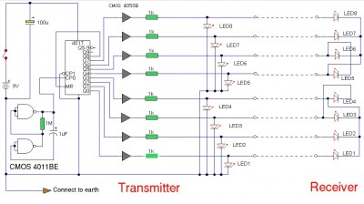
This indicator shows through a dual-LED see if a fuse is intact. The module is designed for 230 V AC. The green LED illuminates when the fuse is still good, the red lights when the fuse is broken. Perhaps...
This circuit utilizes the widely available LM3914 integrated circuit (IC). The LM3914 is straightforward to operate, does not require external voltage regulators due to its built-in voltage regulation, and can be powered by a variety of sources. The LM3914 is...
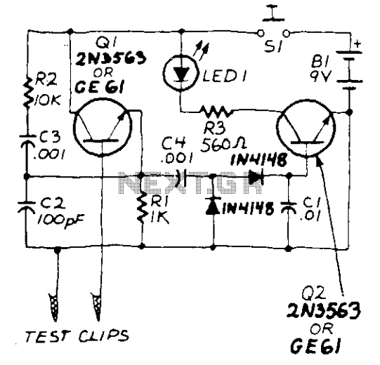
The circuit consists of a transistor Q1, specifically a 2N3563, along with its related components, forming an oscillator that will function only when a suitable crystal is connected to the test clips. The oscillator's output is rectified by two...
The LAN tester circuit can also test cables such as telephone, coaxial, LAN, and others. This circuit uses LEDs as the main indicator device. The LAN tester circuit is designed to verify the integrity and functionality of various types of...

This circuit diagram indicates when the input voltage deviates from two defined limits, V1 and V2. The limits are adjustable, and the circuit is designed to trigger the adjustable window. The supply voltage, Vcc, must be at least 2...
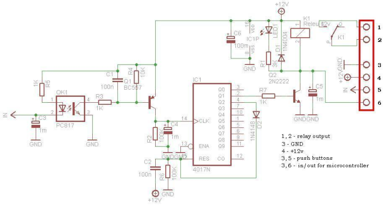
This circuit is operating the room illuminates. The basic component of the circuit is a IC1 (CD4017). Push buttons room are connected by normally wired to the circuit. All circuit is separately by optocoupler, which means that the circuit...
Warning: include(partials/cookie-banner.php): Failed to open stream: Permission denied in /var/www/html/nextgr/view-circuit.php on line 713
Warning: include(): Failed opening 'partials/cookie-banner.php' for inclusion (include_path='.:/usr/share/php') in /var/www/html/nextgr/view-circuit.php on line 713