
ir transmitter circuit

The IR transmitter circuit is designed around the NE555 timer IC, which is configured in an astable mode to produce a continuous square wave output. This output oscillates at a frequency of 38 kHz, which is a common frequency for IR communication, particularly in remote control applications. The NE555 timer has two main resistors (R1 and R2) and a capacitor (C1) connected to its timing pins, which determine the frequency of oscillation.
When the circuit is powered by a 9V battery, the NE555 timer begins to switch its output between high and low states, effectively turning the IR LED on and off rapidly. The IR LED emits infrared light pulses corresponding to the 38 kHz frequency, which can be detected by compatible IR receivers.
To ensure proper operation, the circuit may include additional components such as current-limiting resistors for the IR LED to prevent excessive current flow, and decoupling capacitors to stabilize the power supply and filter out noise. The design can be further enhanced by incorporating a modulation scheme for more complex data transmission, or by using multiple LEDs to increase the transmission range and reliability of the signal.
Overall, this IR transmitter circuit provides a simple yet effective solution for wireless communication applications, leveraging the versatility of the NE555 timer IC in generating a stable frequency output suitable for infrared transmission.This is a schematic of a IR transmitter circuit using IC. The IC used in this circuit is a famous timer IC NE555 which is working as an astable multivibrator in this circuit and producing a 38KHz frequency signal. The circuit starts to produce the signal through IR LED when we connect a 9V battery to the circuit 🔗 External reference
Related Circuits
The ability amplifier has remained functional since it was first introduced in 2002. It is not broken, so there is no reason to fix it. The accompanying photo shows a well-assembled board (known as M27). Utilizing TIP35/36C transistors, the...
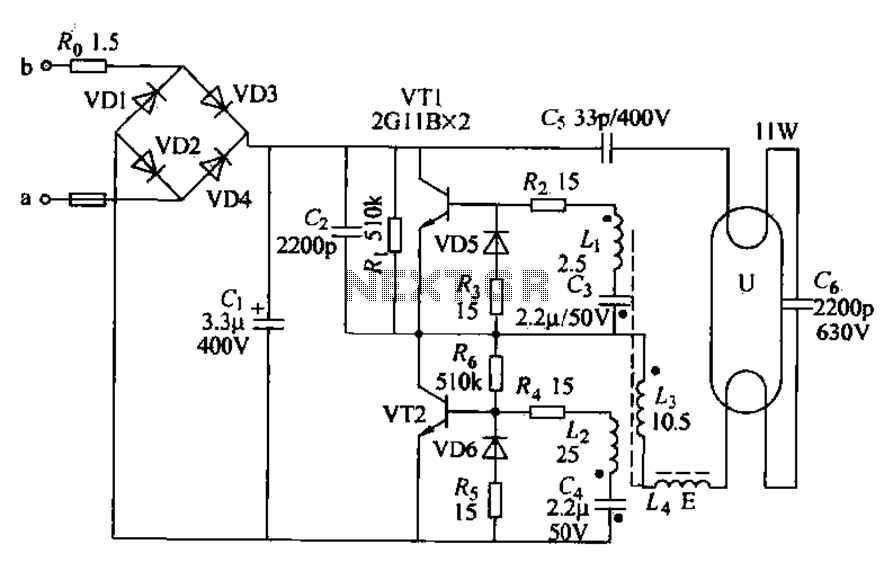
Energy-saving lamps are categorized into self-ballasted compact types and single-ended structures. They can also be classified based on appearance into various forms such as double-tube, four-tube, six-tube types, and others. The lifespan of energy-saving lamps is approximately ten times...
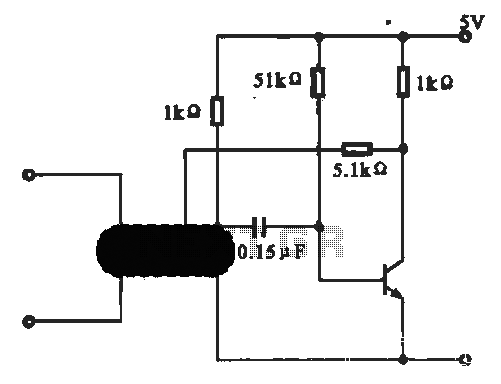
This circuit illustrates an oscillator that is controlled by an optocoupler, utilizing photoelectric coupling to drive a transistor. The oscillator circuit described operates by employing an optocoupler to provide electrical isolation between its input and output stages while allowing control...

The circuit designed for distortion measurements eliminates the fundamental frequency of 1 kHz, enabling the assessment of the residual harmonic levels. Initially, a true RMS meter is employed to measure the 1-kHz input level (E^) by positioning the switch...
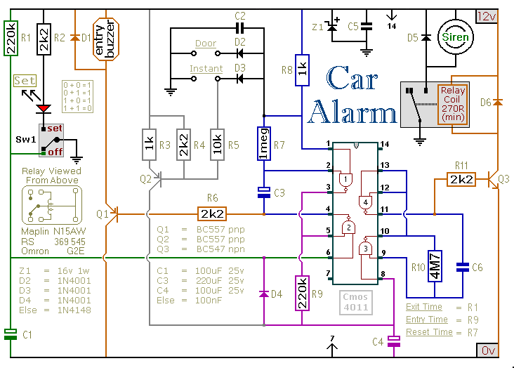
This car alarm circuit includes exit and entry delays, an instant alarm zone, an intermittent siren output, and automatic reset. By incorporating external relays, it is possible to immobilize the vehicle and activate the flashing lights. The car alarm circuit...
This page provides basic information about voltage comparator integrated circuits and is to act as reference material for other circuits. The circuits shown are based on the LM339 Quad Voltage Comparator chip or the LM393 Dual Voltage Comparator chip....