
1Khz Harmonic Distortion Meter Circuit

The circuit operates by utilizing a true RMS meter to accurately gauge the input signal's amplitude at 1 kHz. The design incorporates a switch (SA) that allows the user to toggle between measuring the input signal and assessing the distortion level. In the input position, the true RMS meter captures the voltage level of the fundamental frequency, which serves as a reference point for further analysis.
Once the initial measurement is obtained, the switch is set to the distortion position. This configuration allows the circuit to filter out the fundamental frequency, isolating the harmonic components present in the signal. The 2 kΩ potentiometer plays a crucial role in fine-tuning the circuit; by adjusting it, the user can minimize the output signal to a null point, effectively canceling out the fundamental frequency and focusing solely on the residual harmonics.
After achieving the null condition, the residual level of harmonics can be accurately noted. This value is essential for calculating the Total Harmonic Distortion (THD), which quantifies the extent of distortion present in the signal relative to the fundamental frequency. The calculation typically involves taking the ratio of the power of the harmonic components to the power of the fundamental frequency, often expressed as a percentage.
This circuit is particularly useful in audio applications, where the fidelity of sound reproduction is critical. By enabling precise measurements of distortion levels, it assists engineers and technicians in evaluating and improving the performance of audio equipment, ensuring high-quality sound output. The circuit useful for distortion measurements notches out the fundamental frequency of 1 kHz to allow measurement of the residual level of harmonics. First a true RMS meter is used to measure the 1-kHz input level E^ by setting SA to the input position.
Then, SA is placed in the distortion position and the 2 k potentiometer is adjusted for a null. The residual reading is noted. The THD is then calculated based on the formula:
Related Circuits
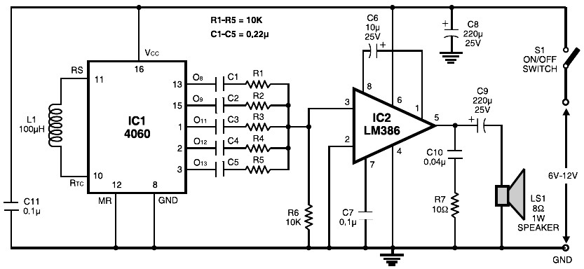
The circuit is built around the popular CMOS oscillator-divider IC 4060 and a small audio amplifier LM386. The IC 4060 functions as a multitone generator. A 100 H inductor is used at the input of the IC 4060, allowing...

This design circuit functions as a sine wave oscillator, providing both sine and square wave outputs across a frequency range from below 20 Hz to above 20 KHz. The oscillation frequency can be easily adjusted by varying a single...
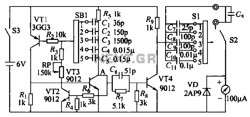
A capacitive measuring instrument is a direct reading device that measures the capacitance of a circuit. This instrument is capable of measuring capacitance values ranging from a few picofarads to 0.1 microfarads, with specific ranges of 25 pF, 100...
There is no substitute for sheer power—low-efficiency speakers, outdoor sound systems, or perhaps the full dynamic range of a high-power amplifier. Whatever the requirement, this super power module should meet the needs. The amplifier can be divided into three...
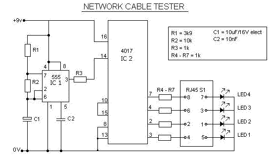
This is a multifunction RJ45 network cable tester designed for testing network cables (RJ45) and telephone cables (RJ11). It is cost-effective and user-friendly. The tester determines whether a network cable is a crossover or straight type by illuminating a...
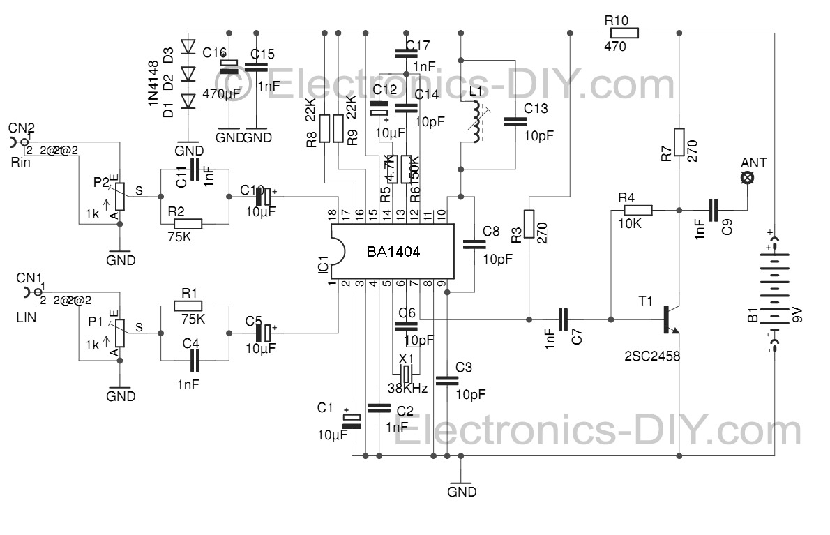
This Stereo FM Transmitter with BA1404 enables the creation of a mini stereo FM station, allowing for wireless audio broadcasting throughout a home. It provides a straightforward method for establishing an audio link without the need for complex wiring....