
JFET-Bipolar Cascode
The JFET-Bipolar Cascode Circuit is an advanced electronic configuration that combines the benefits of both JFET and bipolar transistor technologies to achieve high gain and improved bandwidth performance. In this design, the transconductance amplifier serves as the first stage, where the input signal is processed to produce a current that is proportional to the voltage input. The subsequent current buffer stage ensures that the output current can drive the load without significant signal degradation.
The cascode arrangement is particularly advantageous in this application as it minimizes the effects of parasitic capacitances, specifically the Miller capacitance, which can limit the frequency response of amplifiers. By placing the JFET in a cascode configuration with a bipolar transistor, the circuit maintains a high input impedance while providing a low output impedance, which is critical for driving the CRT effectively.
Furthermore, the incorporation of an m-derived filter is a strategic choice to suppress unwanted frequencies. Stray capacitance in the circuit is utilized in conjunction with a variable inductor to create a filter that selectively attenuates the 4.5 MHz sound frequency. This filtering action is essential in ensuring that the video amplifier focuses solely on the desired video signals, thereby enhancing the overall performance and clarity of the output.
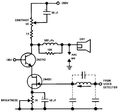
In summary, the JFET-Bipolar Cascode Circuit Diagram represents a sophisticated design that effectively combines multiple electronic principles to deliver high-quality video output while addressing potential frequency interference issues. The careful selection of components and configuration allows for robust performance suitable for CRT applications.The following schematic shows the JFET- Bipolar Cascode Circuit Diagram. The JFET- Bipolar cascode circuit will provide full video output for the CRT cathode drive. Gain is about 90. The cascode is a two-stage amplifier composed of a transconductance amplifier followed by a current buffer. The cascode configuration eliminates Miller capacitance p roblems with the 2N4091 JFET, thus allowing direct drive from the video detector. An m derived filter using stray capacitance and a variable inductor prevents 4. 5 MHz sound frequency from being amplified by the video amplifier. 🔗 External reference
Related Circuits
A cascode amplifier using two MOSFETs is illustrated in the diagram. L2C1 and L3C2 resonate at the operating frequency. The circuit offers advantages such as high gain, low noise figure (NF), and excellent linearity. Q1 and Q2 can be...
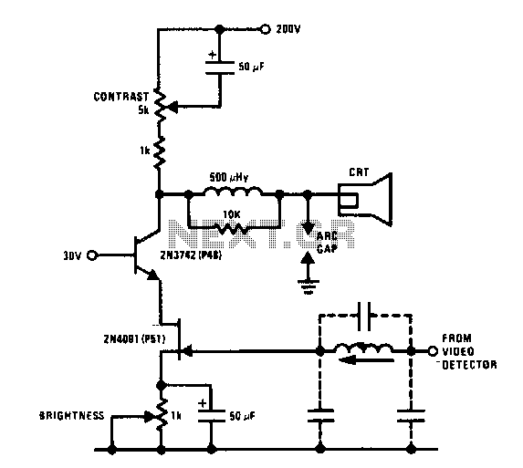
The JFET-bipolar cascode circuit will provide full video output for the CRT cathode drive. Gain is about 90. The cascode configuration eliminates Miller capacitance problems with the 2N4091 JFET, thus allowing direct drive from the video detector. An m-derived...
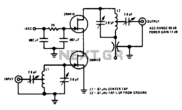
This 200 MHz JFET cascode circuit features low cross-modulation, large signal handling ability, no neutralization, and automatic gain control (AGC) managed by biasing the upper cascode JFET. The only special requirement of this circuit is that the drain-source saturation...
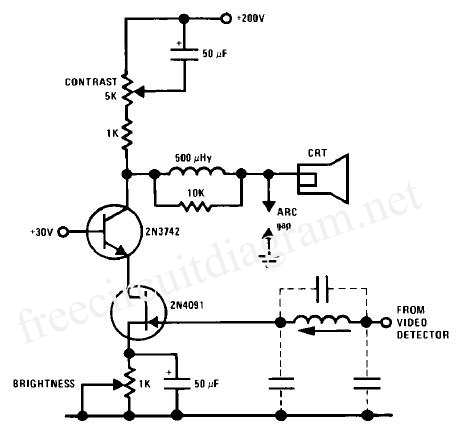
A JFET-bipolar cascode circuit is designed to deliver complete video output for driving the cathode of a CRT. The configuration offers an approximate gain of 90. The cascode arrangement mitigates issues related to the Miller capacitance of the JFET...
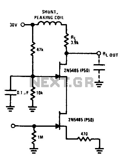
The FET cascode video amplifier exhibits very low input loading and minimizes feedback to nearly zero. The 2N5485 transistor is utilized due to its low capacitance and high transconductance (YfS). Additionally, the bandwidth of this amplifier is constrained by...
Available RC coupling between its two stages can also be directly coupled. This is in addition to the common-emitter total radio circuit configuration, which is widely used. Outside the previously described common-emitter circuit, a total group or common-emitter circuit...
Warning: include(partials/cookie-banner.php): Failed to open stream: Permission denied in /var/www/html/nextgr/view-circuit.php on line 713
Warning: include(): Failed opening 'partials/cookie-banner.php' for inclusion (include_path='.:/usr/share/php') in /var/www/html/nextgr/view-circuit.php on line 713