
Cascode Rf Amplifier
The cascode amplifier configuration is a well-regarded topology in analog circuit design, particularly known for its ability to enhance performance metrics such as gain, bandwidth, and linearity while reducing noise. In this specific design, two MOSFETs are utilized, which allows for improved control over the output characteristics.
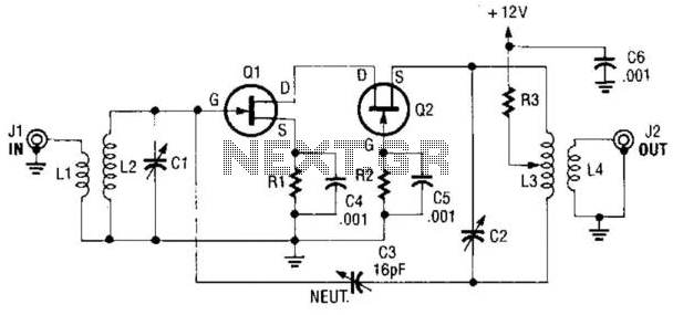
The resonant components L2C1 and L3C2 are critical in defining the frequency response of the amplifier. These components form resonant circuits that can be tuned to the desired operating frequency, ensuring optimal performance within the specified range. The resonant frequency is determined by the values of the inductors (L) and capacitors (C) used, following the standard formula for resonance: f = 1 / (2π√(LC)).
The choice of MOSFETs, specifically the MPF102 or 2N4416, is significant as these devices are characterized by their low threshold voltage and high transconductance, which contribute to the overall gain and efficiency of the amplifier. The cascode arrangement minimizes the Miller effect, which enhances the bandwidth and stability of the amplifier.
Furthermore, the low noise figure is a critical advantage in applications where signal integrity is paramount, such as in RF amplification or sensitive analog signal processing. The configuration's excellent linearity ensures that the output signal remains faithful to the input, making it suitable for high-fidelity applications.
In summary, the described cascode amplifier circuit effectively combines the advantages of MOSFET technology with resonant circuit design to achieve superior performance metrics, making it a valuable choice for a variety of electronic applications. A cascode amplifier using two MOSFETs is shown in the diagram. L2C1 and L3C2 resonate to the frequency in use. The cir cuit has the advantage of good gain, low NF, and excellent linearity. Ql and Q2 can be MPF102 or 2N4416. 🔗 External reference
Related Circuits
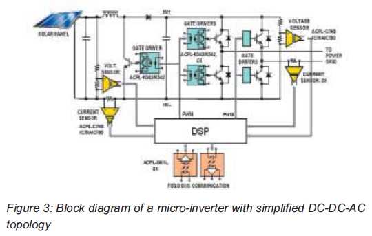
Both help improve efficiency and protect micro-inverters in photovoltaic (PV) solar applications. In 2009, the residential solar photovoltaic (PV) inverter market represented 90 percent of the total PV. The integration of micro-inverters in photovoltaic solar applications has significantly enhanced system...
What is so special? First of all, it has a very low harmonic distortion. Typically, manufacturers indicate the maximum power of their products with a harmonic content of 10%. In contrast, this chip achieves a harmonic distortion of only...
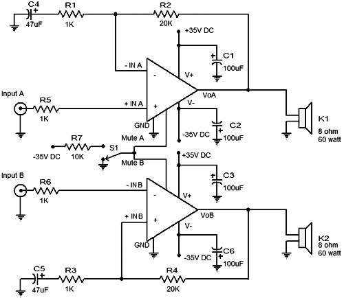
The power amplifier Hi-Fi OCL 120W RMS is designed to operate effectively when paired with a suitable power supply circuit and 8-ohm speakers. This circuit exclusively utilizes transistors without any integrated circuits, resulting in a clean sound output. The...
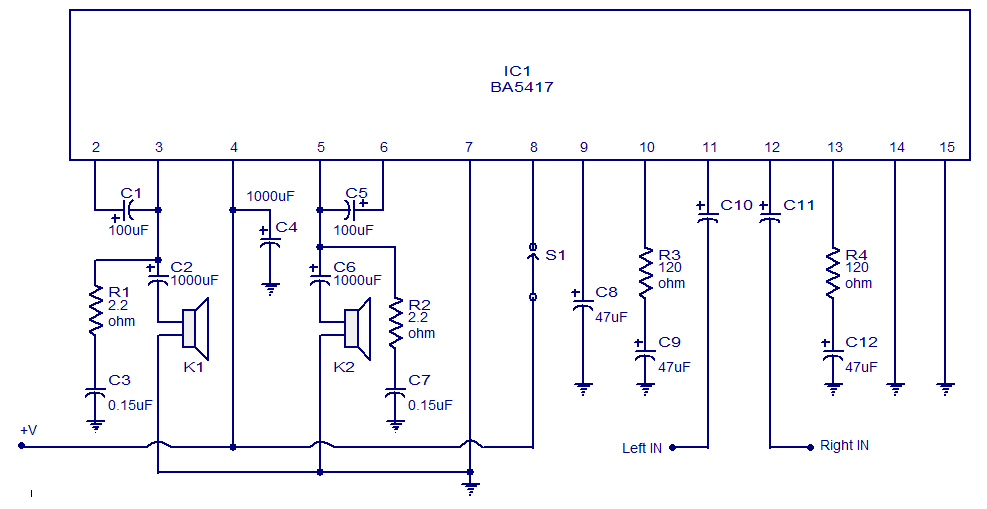
The BA5417 is a stereo amplifier integrated circuit (IC) that features several advantageous characteristics, including thermal shutdown, a standby function, soft clipping, and a wide operating voltage range. It can deliver 5 watts per channel into 4-ohm loudspeakers when...
The circuit presented is experimental and should provide some fun to build and play about with. It has been built and tested and works very well indeed. Please note that it is a low current Class-A opamp and is...
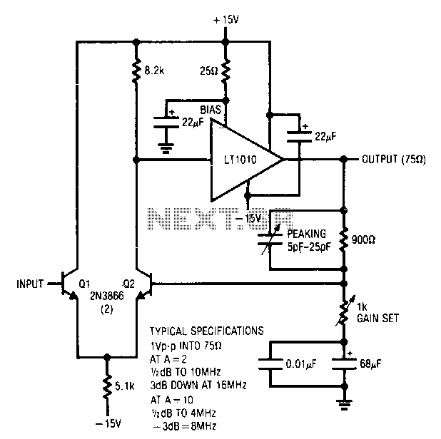
Q1 and Q2 create a differential stage that transitions into the LT1010. The capacitively terminated feedback divider provides a gain of 1, while permitting AC gains of up to 10. With a 20-ohm bias resistor, the circuit outputs 1...
Warning: include(partials/cookie-banner.php): Failed to open stream: Permission denied in /var/www/html/nextgr/view-circuit.php on line 713
Warning: include(): Failed opening 'partials/cookie-banner.php' for inclusion (include_path='.:/usr/share/php') in /var/www/html/nextgr/view-circuit.php on line 713