
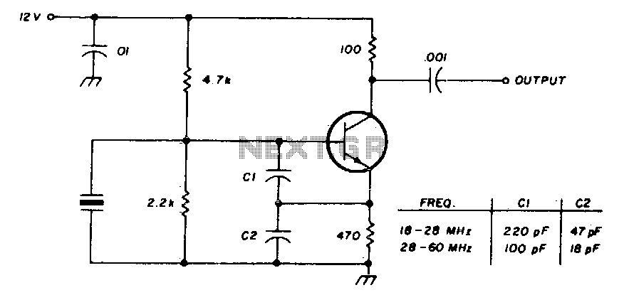
JFET Pierce Crystal Oscillator
The JFET pierce crystal oscillator is a versatile circuit that utilizes a Junction Field Effect Transistor (JFET) to achieve stable oscillation at the frequency determined by the connected crystal. The circuit typically consists of a JFET, a crystal resonator, a few passive components such as resistors and capacitors, and a power supply.
The JFET serves as an amplifier and oscillator, taking advantage of its high input impedance and low noise characteristics. The crystal resonator is connected in the feedback loop of the JFET, establishing the frequency of oscillation. The specific frequency is determined by the crystal's resonant frequency, which can cover a broad range depending on the type of crystal used.
In the circuit, the gate of the JFET is connected to the crystal, and the source is typically grounded. A resistor is placed in the drain circuit to provide the necessary biasing for the JFET to operate in the active region. Additional capacitors may be included to stabilize the oscillation and filter out unwanted noise.
One of the key advantages of this oscillator design is its ability to accommodate various crystal frequencies without the need for circuit modifications. This flexibility makes it suitable for applications requiring different frequencies, such as in communication systems, clock generation, and signal processing.
Overall, the JFET pierce crystal oscillator is a robust and efficient circuit that provides reliable frequency generation across a wide range of applications. Its simplicity and adaptability make it a popular choice among electronics engineers for various oscillator needs.This is a simple JFET pierce crystal oscillator. We can use a wide frequency range of crystal using this circuit without circuit modification. Here is the.. 🔗 External reference
Related Circuits
Hartley oscillators are inductively coupled, variable frequency oscillators that can be series or shunt fed. They feature a center-tapped inductor and a tuning capacitor, which simplifies the circuit construction. The schematic includes a buffer stage and an amplifier stage...
This circuit allows for the testing of quartz resonators within a frequency range of 32 kHz to 24 MHz. The operational status of the quartz resonator is indicated by a diode signaling an LED and an acoustic signal. The circuit...
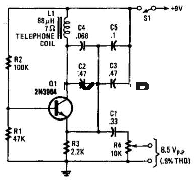
An 88 mH surplus telephone toroidal coil is utilized in a 1 kHz oscillator. It can provide up to 8 V peak-to-peak into a high-impedance load. The total harmonic distortion (THD) is 0.9%. The circuit employs an 88 mH toroidal...
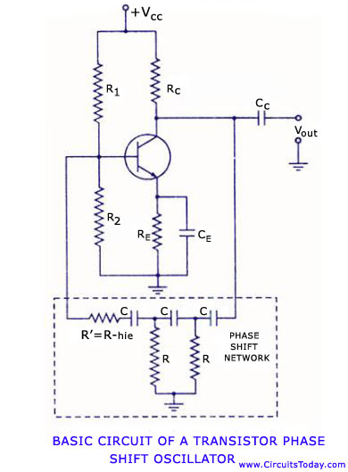
Transistor RC phase shift oscillator. RC phase shift oscillator using operational amplifier. RC phase shift network. Theory and working principle. Circuit diagram. The transistor RC phase shift oscillator is a type of electronic oscillator that generates sine wave signals. This...
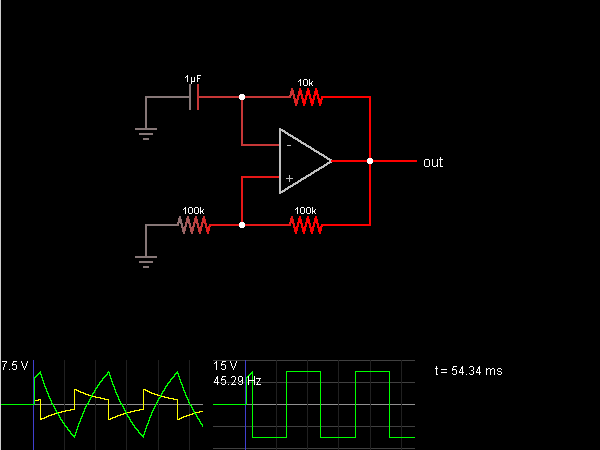
This circuit is an oscillator that generates a square wave. The operational amplifier (op-amp) begins with its two inputs in an undefined state, starting with the non-inverting input slightly higher than the inverting input. The op-amp significantly amplifies this...
International Crystal OF-1 HI oscillator circuit for third-overtone crystals. The circuit does not require inductors. The International Crystal OF-1 HI oscillator circuit is specifically designed to operate with third-overtone crystals, which are capable of generating higher frequency oscillations compared to...