
crystal tester
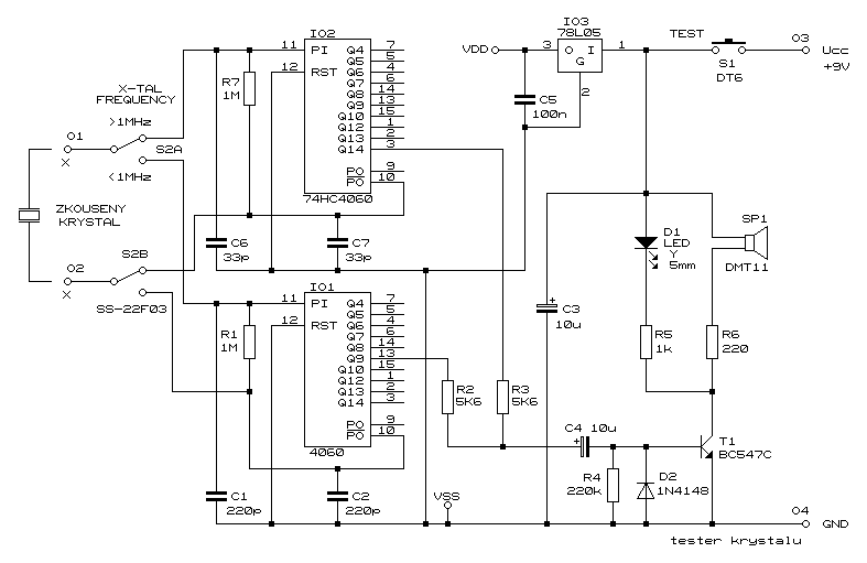
The circuit is designed to facilitate the evaluation of quartz resonators, which are critical components in various electronic applications, particularly in timing and frequency control. The testing process involves applying an input signal to the quartz resonator and measuring its response to determine if it operates within the specified frequency range.
Key components of the circuit include a signal generator, which produces a range of frequencies from 32 kHz to 24 MHz, and an oscillator circuit that engages the quartz resonator under test. The output of the resonator is monitored through a diode that drives an LED indicator. When the resonator is functioning correctly, the LED lights up, confirming the presence of a valid oscillation. Additionally, an acoustic signal is generated, providing an audible confirmation of the resonator's operational status.
The circuit may also incorporate a variable resistor to adjust the sensitivity of the detection circuit, allowing for the testing of resonators with varying quality factors (Q). A capacitor may be included in the design to filter out noise and stabilize the output signal, ensuring accurate readings.
Overall, this circuit serves as an invaluable tool for engineers and technicians involved in the design and maintenance of electronic systems that rely on quartz resonators. Its straightforward design and dual indication method (visual and auditory) enhance usability and efficiency in testing procedures.This circuit enables you to test quartz resonators at the range values from 32kHz to 24MHz. Confirmation of good state of quartz resonator is done by diode signalling LED and acoustic signal.. 🔗 External reference
Related Circuits

A simple yet reliable car battery tester circuit diagram. This circuit utilizes the popular and easily accessible LM3914 integrated circuit (IC). The LM3914 is straightforward to operate, does not require external voltage regulators due to its built-in voltage regulator,...
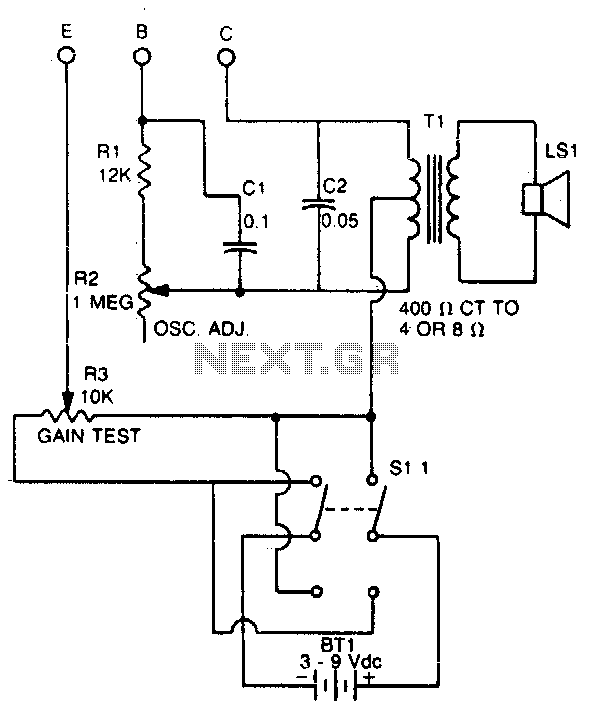
This tester checks the polarity of transistors (PNP or NPN). An audible signal indicates the gain. Additionally, the tester can function as a GO/NO GO tester for matching unmarked devices. The transistor tester is designed to evaluate the polarity and...
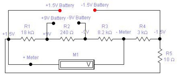
The circuit diagram of a DC battery tester designed by Matthew B. This circuit can measure DC batteries ranging from 1.5V to 9V. Component Parts List: R1 = 18K Ohm, R2 = 240 Ohm, R3 = 8.2K Ohm, R4...
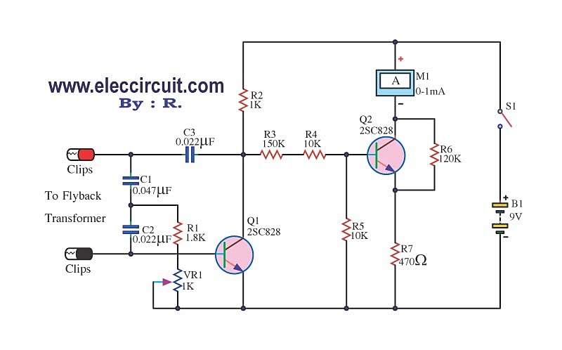
The circuit tests a flyback transformer used in televisions, and it is simple, easy, and inexpensive to construct. A friend who is a TV repairman provided this information. The circuit designed for testing a flyback transformer is essential for diagnosing...
Logic-1 and logic-0 represent the states of digital signals, where logic-1 corresponds to a high voltage close to Vcc, and logic-0 corresponds to a voltage near neutral or ground. Logic-0 cannot be transformed into logic-1, while logic-1 can revert...
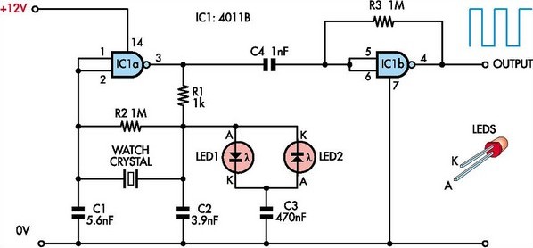
This circuit was designed to enable the use of watch crystals in an existing CMOS oscillator circuit powered by a 12V supply. The challenge arises because these crystals typically operate at a maximum supply voltage of approximately 6V; exceeding...