
Keyer dimmer table lamp circuit
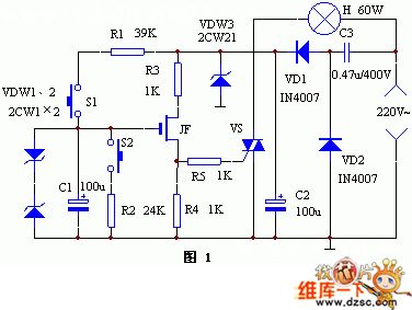
The keyer dimmer table lamp is designed to provide adjustable lighting through a user-friendly interface featuring two touch-sensitive buttons. The circuit operates on a capacitance buck converter principle, which allows for efficient voltage regulation and dimming capabilities.
The touch buttons serve as input controls; one button is designated for dimming the light, while the other increases the brightness. When the dimming button is activated, it triggers a reduction in the output voltage supplied to the lamp, causing the light to gradually weaken. Conversely, activating the brightness button increases the output voltage, resulting in a brighter illumination.
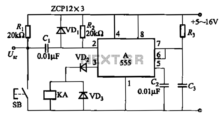
The circuit's core components include diodes VD1 and VD2, which are responsible for rectifying the AC input voltage to a suitable DC voltage level. The capacitors C2 and C3 play a crucial role in smoothing the rectified output, ensuring stable operation and minimizing voltage fluctuations. This arrangement allows for a seamless transition between different brightness levels, enhancing the user experience.
The overall design emphasizes efficiency and reliability, making it suitable for various applications where adjustable lighting is desired, such as in living rooms, bedrooms, or workspaces. The simplicity of the touch interface combined with the effective dimming mechanism offers a modern solution to traditional lamp controls.Keyer dimmer table lamp adopts two touch buttons to adjust the light. The light changes weaken from strong when peopletouch one of the buttons, and it changes strong from weaken when peopletouch the other button. Working principle The principle of this circuit is shown in diagram 1. Capacitance buckDC power supply is composed of VD1, VD2, C2 and C3.. 🔗 External reference
Related Circuits
The circuit indicates two different water temperature trip points by activating LEDs when the specified temperatures are reached. It is built around the LM2904 dual operational amplifier, which is powered by a 12 V automotive system. A thermistor is...

This circuit operates effectively across a broad frequency spectrum. XTAL 1 serves as a fundamental-frequency crystal. Tl and CI are adjusted to match the input frequency. This circuit can be utilized as a straightforward shortwave converter for AM radios,...
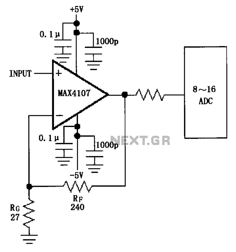
The inverting gain circuit utilizing the MAX4107 is configured as an ADC input buffer. The gain of the amplifier is established by the ratio of resistors RF and RG, which set the gain figure to approximately 10. The inverting gain...
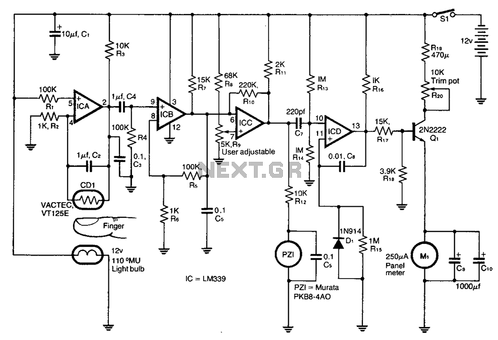
A cadmium sulfide photoresistor (CD1) fingertip can be detected through the filter. CD1 forms part of the sense amplifier feedback network. A section of the sense amplifier (ICA) produces weak signals that may be further amplified by ICB. These...
The 555 integrated circuit is utilized in a delay circuit configuration, functioning as a one-shot timer. The delay time can be adjusted using resistor R3 and capacitor C3. Typical values for R3 range from 1 kΩ to 10 MΩ,...
The circuit for the ball game scoring device is depicted in the accompanying image. This device records and displays the performance of a ball game. The first Nixie tube has two states: it can either be off or display...
Warning: include(partials/cookie-banner.php): Failed to open stream: Permission denied in /var/www/html/nextgr/view-circuit.php on line 713
Warning: include(): Failed opening 'partials/cookie-banner.php' for inclusion (include_path='.:/usr/share/php') in /var/www/html/nextgr/view-circuit.php on line 713