
Klipsch Promedia V5.1 Amplifier Repair
Below are the interconnections for the system. The control pod and the satellite speakers shown are separate units; all other connections are internal to the subwoofer box. There is not much you can do about repairing the V5. 1 control pod. Klipsch moved all the pre-amplifier circuitry into the sub-woofer box. The control pod is just a remote control head now. A serial data stream from the control pod relays commands to adjust the volume level of the various channels.
All the manual inputs are rotary encoders that are monitored by a microcontroller. With the exception of the encoders and a few transistors everything is done by the microcontroller program, which you can`t buy from Klipsch and for which we don`t have any data. Maybe someone can come up with an analog replacement circuit. The following block diagram of the control pods is marked to show basic operation of the pods and the differences between them.
Click on the block diagram, or here to get schematic diagrams of the two control pods. The diagram for the V5. 1 DIN plug comes from tracing of the wires by Evan Shultz on his plug. Pins are identified by using the pin numbers on the control pod circuit board connector, J2, then continuing the sequence with the signals from J6 on the standard pod or J1 on the Ultra pod. The V5. 1 I/O board is very busy. The control pod is just that on the V5. 1, a control pod, so all the audio preamplifiers and headphone amplifiers had to be moved into the subwoofer box.
Breaking the I/O board down, we have seven sub-sections: the front-channel preamplifiers, the rear-channel preamplifiers, the center-channel preamplifier, the subwoofer filter, the headphone amplifiers, the headphone/control-pod power supply, and the control-pod, serial-data circuits. All the preamplifiers are similar. A 2X gain stage, like center-channel U4:3, supplies a signal to the subwoofer filter and to the serial-data-controlled level adjuster U5.
The level-adjusted signal is fed to the headphone amplifier summing circuit and to a high-pass filter that in turn drives the channel`s power amplifier. The front-channel preamplifier adds summing amplifiers U3:1 and U3:2 to inject the subwoofer input and the auxililiary input from the control pod into the front-channel signal.
Subwoofer filter (U6:3, U5:6, U1:3, U1:2 and U1:1) is level controlled by U5:6. The filter is a a second-order, high-pass, Sallen-Key filter followed by a a second-order, low-pass, Sallen-Key filter resulting in a very narrow low frequency bandpass filter. U6:3 is a summing amplifier to combine the signals from the individual channel preamplifiers. The headphone amplifiers are low-powered, push-pull, AB circuits with summed inputs from all the various preamplifiers.
Relay K1 controls the function of the auxiliary-input/headphone-output jack on the control pod. In the un-activated state, K1 passes audio signals from the dual-purpose jack to the front-channel summing amplifiers U3:1 and U3:2. When headphones are selected on the control pod, the pod sends a HP-MODE, high-level logic signal to Q1.
This activates K1 and the auxilary-input/headphone-output jack on the control pod is connected to the headphone amplifier outputs. The headphone amplifiers and the I/0 board preamplifiers get their +/- 15V power from a power supply separate from the AC-DC converter.
This low-power regulator is constantly active, and sourced by the transformer on the line-filter board. In this manner temperature inside the subwoofer box is reduced during the non-use periods when there is no air movement provided by the subwoofer speaker cone.
The + 🔗 External reference
Related Circuits
This is a 7-tube, 20-watt amplifier that must be used in conjunction with a preamplifier featuring volume and tone controls. A suitable recommendation is a 6-tube preamplifier. This amplifier utilizes 6BQ5 output tubes and employs a 5U4-G rectifier to...
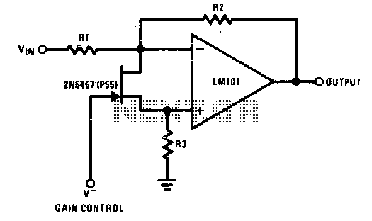
The 2N5457 functions as a voltage-variable resistor with a maximum RdS of 800 ohms. Given that the differential voltage on the LM101 is in the low millivolt range, the 2N5457 JFET exhibits linear resistance over several decades, offering excellent...
Can be directly connected to CD players, tuners and tape recorders. Tested with several headphone models of different impedance: 32, 100, 245, 300, 600 & 2000 Ohm. Schematic shows left channel only. More: B1, SW1, J1 & C3 are...
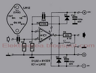
This is an 80W power amplifier OCL circuit that utilizes the integrated circuit LM12. It effectively enhances bass and treble performance. When connected to a CD player, it produces high-quality sound, especially when paired with a good pre-tone control....
If you still like to spin vinyl and features a turntable, but the amplifier has no more input for a turntable is below a switching solution. We used a NE5532 to a simple stereo RIAA phono preamp to build....
This car stereo booster utilizes an LM2896 integrated circuit, which features two amplifiers. It operates with supply voltages ranging from 3 to 15 volts. The power output is 2.5 watts per channel when connected to an 8-ohm load at...
Warning: include(partials/cookie-banner.php): Failed to open stream: Permission denied in /var/www/html/nextgr/view-circuit.php on line 713
Warning: include(): Failed opening 'partials/cookie-banner.php' for inclusion (include_path='.:/usr/share/php') in /var/www/html/nextgr/view-circuit.php on line 713