
Headphone Amplifier

The described circuit is designed for audio applications, allowing direct connection to various sources such as CD players, tuners, and tape recorders. The circuit has been tested with a range of headphone impedances, demonstrating compatibility with loads of 32, 100, 245, 300, 600, and 2000 Ohms. The schematic provided focuses on the left audio channel, indicating that the right channel shares common components for a balanced stereo output.
Key components include B1 (the power supply), SW1 (a switch for power control), J1 (the headphone jack), and C3 (a coupling capacitor), which are utilized in both channels. The design includes a resistor, R3, whose value is critical for ensuring optimal performance with different headphone impedances. For headphones with an impedance of up to 300 Ohms, the resistor value has been appropriately calculated. However, for higher impedance headphones, specifically those rated at 600 Ohms or more, it is recommended to adjust the value of R3 to 100K Ohms to maintain audio fidelity and prevent distortion.
This circuit may also benefit from modifications or upgrades, as indicated by suggestions from users such as Mike Baum. Such enhancements could lead to improved performance characteristics, making the design adaptable for various audio applications. Overall, the circuit's straightforward design and component selection facilitate a reliable and effective solution for connecting headphones to audio sources.Can be directly connected to CD players, tuners and tape recorders. Tested with several headphone models of different impedance: 32, 100, 245, 300, 600 & 2000 Ohm. Schematic shows left channel only. # B1, SW1, J1 & C3 are common to both channels. # R3 value was calculated for headphone impedance up to 300 Ohm. Using 600 Ohm loads or higher, change R3 value to 100K. # An interesting upgrade for this circuit was suggested by Mike Baum, NY USA. Th 🔗 External reference
Related Circuits
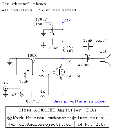
This weblog discusses electronic circuit schematics, PCB design, DIY kits, and electronic project diagrams. It features a simple Class A MOSFET amplifier using the 2SK1058 component. The circuit operates with a 24V supply voltage at high current. It incorporates...
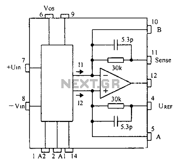
Based on the CNC programming, a gain instrumentation amplifier circuit diagram utilizing the PGA202/203 is presented. The PGA202/203 series of programmable gain amplifiers are designed for high-performance applications requiring precise signal amplification. These integrated circuits offer a wide range of...
It is important to note that there is limited protection circuitry and fuses in this amplifier. A short turn-on delay for the output power supply is included to minimize thumps, along with a couple of line fuses, but no...
The three circuits described provide a constant current to the LED (or LEDs) when the supply voltage reaches 15V or higher. The second and third circuits can be activated or deactivated through the input line by turning on the...
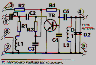
These frequencies include TV in VHF and UHF, as well as the radio broadcasting frequencies in the 88 - 108 MHz FM band. Component: Resistor, IC. The circuit described operates within the VHF (Very High Frequency) and UHF (Ultra High...
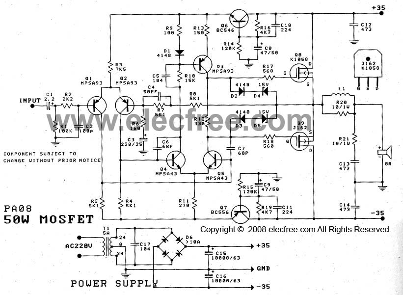
The 50W Power Amplifier OCL Mosfet (K1058 + J162) is simple to construct and cost-effective. It requires a power supply of +35V and -35V at 2A. The Power Mosfet used in this design is K1058 and J162. The 50W OCL...