
KMotion Connectors
The typical current consumption is 0.7 Amps when no user input/output is connected. Additional current may be necessary depending on the amount of digital input/output and analog +/- 15V consumed by the user. The board generates up to 2 watts of +/- 15 volts from the 5V supply, with most of this power available for external use. A 5V supply rated at 2.5A should be adequate under all conditions. The 12V input is not utilized internally by the board but is routed to pins on the 37-pin DB Motor connector and the 16-pin Aux Connector for user convenience. The 5V power is also routed to the 37-pin DB Motor connector, allowing for power application at whichever connector is more accessible. This connector is rated for 6.5 Amps per connection; if more total motor current is needed, power should be routed externally to the 37-pin DB Supply 0-3 inputs directly. This connector is a standard PC-disk drive power connector, facilitating the use of inexpensive PC power supplies to drive the board and small to medium-sized motors (less than 12V) with minimal external connections. The PC power supply can be plugged in here, with the +12V signals on the DB37 Pin connector jumpered to the desired motor supply inputs, followed by connecting the motors. The KMotion motion control board functions as a 4-axis motor controller, comprising 8 full bridge drivers. A full bridge driver can apply either a positive or negative voltage to a load using a single positive supply, with the load connected across the OUTA and OUTB terminals. The 8 full bridge drivers are organized into 4 pairs, with each pair associated with a motor axis. Certain motor types, such as stepper motors or 3-phase motors, require more than one full bridge for operation. Each axis, along with its pair of full bridge drivers, shares a common power supply pin, heat sink, encoder input, and current sensing circuitry. Different types of motors (DC-Brush, 3-phase brushless, or stepper) may be used on each axis, with varying supply voltages (12-55V DC). For a DC-Brush motor, only one full bridge driver is utilized, leaving the other unconnected. 3-phase brushless motors utilize 1.5 full bridges (3 half bridges), while stepper motors require both full bridges due to their two coils. Additionally, the connector includes a PBRST# signal, which can be shorted to ground to reset the board; this signal is internally de-bounced. Typically, the on-board power-up reset is sufficient, allowing this pin to remain disconnected. Connecting this pin to the DOG pin activates the on-board watchdog circuitry, which automatically resets the board if no DSP/FPGA activity is detected for one second. This feature is generally not necessary and can be left disconnected. The connector is also used for advanced debugging with an XDS510 JTAG in-circuit emulator. A small amount of regulated 3.3V (less than 0.5 Amp) is available on this connector for external use. The system supports 4 channels of +/- 10V analog inputs, 4 channels of +/- 10V analog outputs, 4 channels of 0-4V analog outputs, 22 LVTTL bi-directional digital I/O, and +5, +15, -15 power supply outputs. Many digital I/O bits are pre-defined for encoder, home, or limit inputs but can be repurposed as general-purpose I/O if not required for specific applications. Digital outputs can sink or source 10 mA and are LVTTL (3.3V) but tolerate 5V levels. The KMotion board includes two SPST switches to ground, capable of driving up to 30V at 2A. One switch is dedicated to driving the cooling fan, while the other is available for additional uses. If the fan is unnecessary for the application (when less than 2 Amps is drawn on all axes), it may be repurposed for external loads. Each switch is connected to a 2-pin connector, with one pin linked to the 5V supply and the other switched to ground. If a 5V load (e.g., a 5V fan) is required, it can be connected directly across the two pins. For loads requiring different voltages, external user supply considerations must be taken into account.
The KMotion motion control board is designed for flexibility and ease of use in motor control applications. The architecture allows for various motor types and configurations, catering to a wide range of operational needs. The use of full bridge drivers enables effective control of motor direction and speed, while the integrated power supply options simplify the overall design and reduce the need for additional components. The ability to connect external power supplies and the inclusion of multiple analog and digital I/O channels provide extensive interfacing capabilities for integration into larger systems. Furthermore, the board's debugging features facilitate development and troubleshooting, ensuring that users can efficiently manage their motion control tasks. The layout and design of the connectors enhance usability, making it straightforward to connect and configure the necessary components for diverse applications. Overall, the KMotion motion control board stands out as a versatile solution for controlling multiple motor types with varying requirements.Typical current = 0. 7Amps with no user I/O connected. More current may be required dependent on the amount of Digital I/O and Analog +/- 15V consumed by the user. Up to 2 watts of +/-15 volts is generated on board from this 5V supply (most of which is available for external use).
5V @ 2. 5A should be more than sufficient under all conditions. The 1 2V input is not used internally by the board, but is routed to pins on the 37pin DB Motor connector and the 16 pin Aux Connector for the convenience of the user. 5V power is also routed to the 37pin DB Motor connector, 5V power may be applied at whichever connector is more convenient.
This connector is only rated for 6. 5Amps per connection, if more total motor current is required, power should be externally routed to the 37pin DB Supply 0-3 inputs directly. This connector is a standard PC-disk drive power connector which makes it easy to drive the board and small to medium size motors (< 12V) with an inexpensive PC power supply and very few external connections.
Simply plug the PC power supply here, jumper the +12V signals on the DB37 Pin connector to the desired motor supply inputs, and connect your motors. The KMotion motion control board is basically a 4 axis Motor controller that consists of 8 full bridge drivers (see figure 1).
A full bridge driver is able to apply a positive or negative voltage to a load using only a single positive supply. The load is connected across the OUTA and OUTB terminals. The 8 full bridge drivers are grouped into 4 pairs, where a pair of full bridge drivers are associated with a motor axis.
This is because some types of motors (stepper motors or 3-phase motors require more than a single full bridge to drive them). Each axis (and pair of full bridge drivers) share a common power supply pin, heat sink, encoder input, and current sense circuitry.
Each axis may be of a different type (DC-Brush, 3-phase brushless, or stepper) and may use a different supply voltage (12-55V DC). If a DC-Brush motor is used for an axis only one of the full bridge drivers are used, the other is left unconnected.
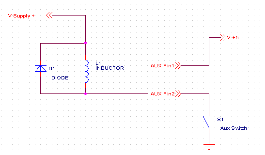
3-phase brushless motors use 1 ½ full bridges (3 - half bridges), and stepper motors have 2 coils which require both full bridges. Also available on this connector is PBRST#. Short PBRST# to ground to reset the board. This signal is internally de-bounced. Under normal conditions, on-board power up reset should suffice so this pin may be left disconnected.
Also connecting this pin to the DOG pin will enable the on board watchdog circuitry, whenever there is no DSP/FPGA activity detected for 1 second the board will be automatically reset. This is not normally required and may be left disconnected. This connector is only used for advanced debugging using an XDS510 JTAG in circuit emulator. A small amount of regulated 3. 3V (<0. 5 Amp) is available on this connector if needed for external use. 4 channels of +/- 10V analog inputs, 4 channels of +/- 10V analog outputs, 4 channels of 0-4V analog outputs, 22 LVTTL bi-directional digital I/O, and +5, +15, -15 power supply outputs.
Many Digital I/O bits are pre-defined as encoder, home, or limit inputs (see table below) but if not required for the particular application may be used as general purpose I/O. Digital Outputs may sink/source 10 ma. Digital I/O is LVTTL (3. 3V) but is 5 V tolerant. Kmotion contains two SPST switches to ground capable of driving up to 30V @ 2A. One is dedicated to driving the cooling fan and one is available for another use. If the fan is not required by the application (less than 2Amps drawn on all axis) it may also be used to drive an external load.
Each of the switches is connected to a 2 pin connector. One of the pins is connected to the 5V supply and the other pin is switched to ground. If the load requires 5V (i. e. a 5V fan) it may be connected directly across the 2 pins. If other than a 5V load is required, then external user sup 🔗 External reference
The KMotion motion control board is designed for flexibility and ease of use in motor control applications. The architecture allows for various motor types and configurations, catering to a wide range of operational needs. The use of full bridge drivers enables effective control of motor direction and speed, while the integrated power supply options simplify the overall design and reduce the need for additional components. The ability to connect external power supplies and the inclusion of multiple analog and digital I/O channels provide extensive interfacing capabilities for integration into larger systems. Furthermore, the board's debugging features facilitate development and troubleshooting, ensuring that users can efficiently manage their motion control tasks. The layout and design of the connectors enhance usability, making it straightforward to connect and configure the necessary components for diverse applications. Overall, the KMotion motion control board stands out as a versatile solution for controlling multiple motor types with varying requirements.Typical current = 0. 7Amps with no user I/O connected. More current may be required dependent on the amount of Digital I/O and Analog +/- 15V consumed by the user. Up to 2 watts of +/-15 volts is generated on board from this 5V supply (most of which is available for external use).
5V @ 2. 5A should be more than sufficient under all conditions. The 1 2V input is not used internally by the board, but is routed to pins on the 37pin DB Motor connector and the 16 pin Aux Connector for the convenience of the user. 5V power is also routed to the 37pin DB Motor connector, 5V power may be applied at whichever connector is more convenient.
This connector is only rated for 6. 5Amps per connection, if more total motor current is required, power should be externally routed to the 37pin DB Supply 0-3 inputs directly. This connector is a standard PC-disk drive power connector which makes it easy to drive the board and small to medium size motors (< 12V) with an inexpensive PC power supply and very few external connections.
Simply plug the PC power supply here, jumper the +12V signals on the DB37 Pin connector to the desired motor supply inputs, and connect your motors. The KMotion motion control board is basically a 4 axis Motor controller that consists of 8 full bridge drivers (see figure 1).
A full bridge driver is able to apply a positive or negative voltage to a load using only a single positive supply. The load is connected across the OUTA and OUTB terminals. The 8 full bridge drivers are grouped into 4 pairs, where a pair of full bridge drivers are associated with a motor axis.
This is because some types of motors (stepper motors or 3-phase motors require more than a single full bridge to drive them). Each axis (and pair of full bridge drivers) share a common power supply pin, heat sink, encoder input, and current sense circuitry.
Each axis may be of a different type (DC-Brush, 3-phase brushless, or stepper) and may use a different supply voltage (12-55V DC). If a DC-Brush motor is used for an axis only one of the full bridge drivers are used, the other is left unconnected.
3-phase brushless motors use 1 ½ full bridges (3 - half bridges), and stepper motors have 2 coils which require both full bridges. Also available on this connector is PBRST#. Short PBRST# to ground to reset the board. This signal is internally de-bounced. Under normal conditions, on-board power up reset should suffice so this pin may be left disconnected.
Also connecting this pin to the DOG pin will enable the on board watchdog circuitry, whenever there is no DSP/FPGA activity detected for 1 second the board will be automatically reset. This is not normally required and may be left disconnected. This connector is only used for advanced debugging using an XDS510 JTAG in circuit emulator. A small amount of regulated 3. 3V (<0. 5 Amp) is available on this connector if needed for external use. 4 channels of +/- 10V analog inputs, 4 channels of +/- 10V analog outputs, 4 channels of 0-4V analog outputs, 22 LVTTL bi-directional digital I/O, and +5, +15, -15 power supply outputs.
Many Digital I/O bits are pre-defined as encoder, home, or limit inputs (see table below) but if not required for the particular application may be used as general purpose I/O. Digital Outputs may sink/source 10 ma. Digital I/O is LVTTL (3. 3V) but is 5 V tolerant. Kmotion contains two SPST switches to ground capable of driving up to 30V @ 2A. One is dedicated to driving the cooling fan and one is available for another use. If the fan is not required by the application (less than 2Amps drawn on all axis) it may also be used to drive an external load.
Each of the switches is connected to a 2 pin connector. One of the pins is connected to the 5V supply and the other pin is switched to ground. If the load requires 5V (i. e. a 5V fan) it may be connected directly across the 2 pins. If other than a 5V load is required, then external user sup 🔗 External reference
Related Circuits
This article discusses the Lammert Bies - Computer Interfacing (RS485). The content is straightforward and informative. The components mentioned in this article can enhance understanding. For instance, readers can find and purchase RS485 components. The article also covers the...
A 1971 Lincoln Continental 4-door is experiencing a complete power failure inside the vehicle, particularly affecting the ignition switch. The battery cables, post connectors, and fusible link have been checked and are functioning correctly. All fuses in the fuse...