
1971 lincoln continental: post connectors fuse box good cant find

The troubleshooting of the power failure in the 1971 Lincoln Continental requires a systematic approach to identify the root cause of the electrical issue. The absence of power in the vehicle, particularly at the ignition switch, suggests a disruption in the main power distribution circuit. The initial step involves confirming the integrity of the battery and its connections, which have already been verified as functional. The next focus should be on the wiring leading from the battery to the fuse box, including any potential fusible links that may be hidden within the harness.
The cigarette lighter circuit, which was previously investigated, could provide clues to the overall wiring structure. It is essential to check the continuity of the wires leading from the ignition switch to the fuse box, as well as the connections to the circuit breakers. If the circuit breakers are not providing power, they may need to be tested for continuity and functionality.
In the absence of a specific wiring diagram for the 1971 model, utilizing the 1965 diagram as a reference could yield valuable insights, especially since many components and their configurations remained consistent across these model years. It is advisable to trace the wiring from the ignition switch to the fuse box and identify the distribution points for power within the vehicle.
Should there be no power detected at the fuse box, it may be necessary to consider the possibility of a corroded or damaged main supply conductor. The suggestion to run a test wire from the starter solenoid to the fuse box is a practical approach to bypass any potential breaks in the circuit. However, caution should be exercised to ensure that the wire used is adequately rated for the current load, and the inclusion of a fuse will provide additional protection against overload conditions.
In conclusion, a thorough investigation of the vehicle's wiring, focusing on the main power distribution circuit and the connections to the ignition switch, is essential for resolving the power failure issue. The use of diagnostic tools such as a volt/ohm meter and a test light will facilitate the identification of faults within the electrical system, ultimately leading to a successful resolution of the problem.A 1971 lincoln continental 4dr, i am getting no power inside the car mainly ignition switch, i checked battery cables, post connectors, and fusible link by battery all check out good. all fuses in fuse box good. not sure about the circuit breakers though i dont think they feed the ignition switch but cant find wiring diagrams.
Well at firstblush no wiring diagram out of 3 major data bases :-( I will still see if I can find it somewhere. I did find this note (I am not sure it applys to the problem) but worth looking at: PS- 1965 is as close as I have come to a wiring diagram so far. That may work because they did not change them much back then. I will send if you want the 1965 diagram You might want to try this link. They had a donor that gave stacks of data on the lincolons (including yours. You have to join to get the data. You might want to check it out: Basically i turn the key and nothing happens no lights turn on nothing almost as if the battery died.
even stuff thats supposed to work with key off like power seat doesnt work no dome lights nothing. The problem started when i was taking apart the ash tray to find out what was wrong wit the cig. Lighter. Come to find out the cig. Lighter was never wired up and the wires were just hannging. so i preceded to install the new one but then tried to turn the key to on pos to see which wire had power (didnt have any wires connected only unplugged 2 of the lights that are in the ash tray) Sounds like the Main supply conductor has corroded and opened up. You really need a wiring schematic to figure this one out. These are the one a guy like me just do (from the seat of our pants) so to speak with a volt/ohm meter a test light and a lot of patience.
I could see if I can find you a manual if you want There is a OPEN MAIN supply circuit somewhere in the vehicle. While I realize that there could be some differences between a 1965 and a 1971 I am going to post the 2 pages of the Master Diagram for the 1965.
This will give you an idea of how they were all wired back in the day. Followin the schematic it looks like the cig. lighter is fed through a fuse in the fuse block and the cig lighter light is just spliced to the interior lights. now the only circuit breaker i see are the ones in the fuse block are there any anywhere else Thanks for the help by the way much appreciated.
hopefully figure this out soon. PS- I am out in the shop and will check in once in a while. Without having the actual proper schematic I cannot tell you if there are other circuit brakers or fusibible links besides the obvious ones. Lincoln was famous for sticking them all over the place. I would have to have the vehicle to trace it down myself. Ok double check circuit breakers ok. but checked and getting no power to fuse box. cant find anymore fusible liks or other circuit breakers. the start er. solenoid on my car is on rhe starter and not fender mounted like the older ones. theres a red and brown wire coming from it. im assuming one is signal from ign switch and other possible power for acc. niether has power. i was thinking to possibly add a fused jumper to see if i can bypass any breaks or bad fusible links Well it wired like a GM then.
One of those fairly large wires at the solenoid is the MAIN feed for the entire system. If there is power there at the solenoid and no power at the fuse panel and/or the headlamps (sometimes they split it off at the headlamps) then yes I would run a test wire from the solenoid or the positive battery post to the main feed to the fuse and/or headlamp feed and see what happens. There is probably a fusible link buried in the harness somewhere. Make sure if you run a test wire and things start working that you run a heavy enough primary insulated wire so as not to over heat the wire.
Personally I would put a 50 Amp in line fuse in the PERMANENT bypass wire if that is what you end up with. Solder the ends and use s 🔗 External reference
Related Circuits
The TMB-1 is an RF amplifier unit and receiving accessory compatible with low-impedance broadband loops, high-impedance terminated loops (such as Pennant, Flag, or Kaz Delta), and whip (telescoping rod) antennas. This design is optimized for operation within the frequency...
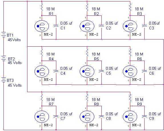
This box is a set of nine relaxation oscillators. It blinks random patterns and looks cool. When the voltage on the capacitors charge to 65 volts, the neon gas ionizes and discharges the capacitors to 55 volts. The frequency...
This circuit is designed to protect a power supply or battery. The electric current will be interrupted by a relay when a short circuit occurs. Relays must be selected with a voltage rating equal to the input voltage. It...
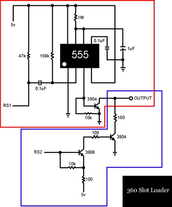
A slot-loading Xbox 360 features a mechanism similar to that of a MacBook, where a CD or DVD is inserted into a thin auto-loading slot rather than using a button to extend a mechanical tray. In contrast, the Xbox...

A 2008 USA Nissan Pathfinder (VIN: 5N1AR18B28C628086) is experiencing issues with the power-assisted mechanism for closing the lift gate (trunk, rear door). The problem began approximately two months ago. The vehicle was taken to Willowdale Nissan in Thornhill, Ontario,...
The headlights of a 2001 Chevy S10 sometimes function and sometimes do not, along with the dashboard indicator light. All other lights are operational. The headlight switch, fuse, and relay have been replaced, and the headlight bulbs have been...