
lamp dimmer
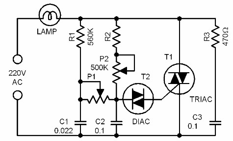
The dimmer circuit utilizes a triac as the primary switching component, which is capable of controlling AC loads by allowing current to flow in both directions when triggered. The design aims to enhance the performance of the triac by lowering the required triggering voltage from the standard 70V to approximately 35V. This reduction is achieved through the strategic addition of resistors, capacitors, and a potentiometer, which work together to modify the triggering characteristics of the triac.
Component R1 serves as a current-limiting resistor, ensuring that the current flowing into the gate of the triac remains within safe limits. C1 acts as a timing capacitor that, in conjunction with R1, creates a delay in the triggering of the triac, allowing for a smooth dimming effect. The potentiometer P1 can be adjusted to fine-tune the phase angle at which the triac is triggered, thereby controlling the amount of power delivered to the load.
The circuit must be housed in an insulating enclosure to prevent electrical hazards, given that it operates at a high voltage of 220 volts. Safety precautions should be taken to ensure that all components are rated for the voltage and current levels present in the circuit.
Applications of this dimmer circuit include not only the control of speed in electric drills and sewing machines but also in various other devices that require adjustable speed or brightness. For example, it can be utilized in lighting systems to provide variable illumination levels or in hobbyist projects where motor speed control is necessary. The versatility of this design makes it a valuable addition to any electronics toolkit.This is not just another dimmer circuit. The improved design of this dimmer circuit enables its triac to be triggered with lower voltage values. Normally, the triggering voltage of a triac is around 70V. In some applications though, it is desirable to use a lower voltage in triggering the triac. A trick is used to achieve this effect in this circu it: the addition of the components R1, C1 and P1. Due to this, the trigger value can be pulled down to around 35V. Construct the circuit and put it in a highly insulating box. Remember, the circuit is working with 220 volts! For P2 use a special potentiometer with a plastic shaft. There are lots of practical applications for this circuit. One typical application is controlling the speed of an ordinary electric drill machine. It can also be used to control the speed of a sewing machine, or the electric motor in a model boat, etc. 🔗 External reference
Related Circuits

In many vehicles, the boot light remains illuminated until the lid is fully closed. It is common to inadvertently leave the lid slightly open while unloading, which can lead to a drained battery if the car is not used...
Flashing frequency can be varied by changing R1 value in the 1M - 4M7 range. This circuit is very efficient when driving a small 3.2V incandescent lamp. In this case omit the LED and R3, connecting the bulb across...
This circuit operates at potentially lethal 220V AC mains voltage. The circuit should be built and used only by individuals who know how to safely work with such dangerous voltages and how to construct the circuit to ensure safety....

Several individuals have struggled to locate the transformer necessary for the Black Light project. Consequently, an investigation was conducted to identify a fluorescent lamp driver that does not necessitate any specialized components. A suitable option was discovered in Electronics...
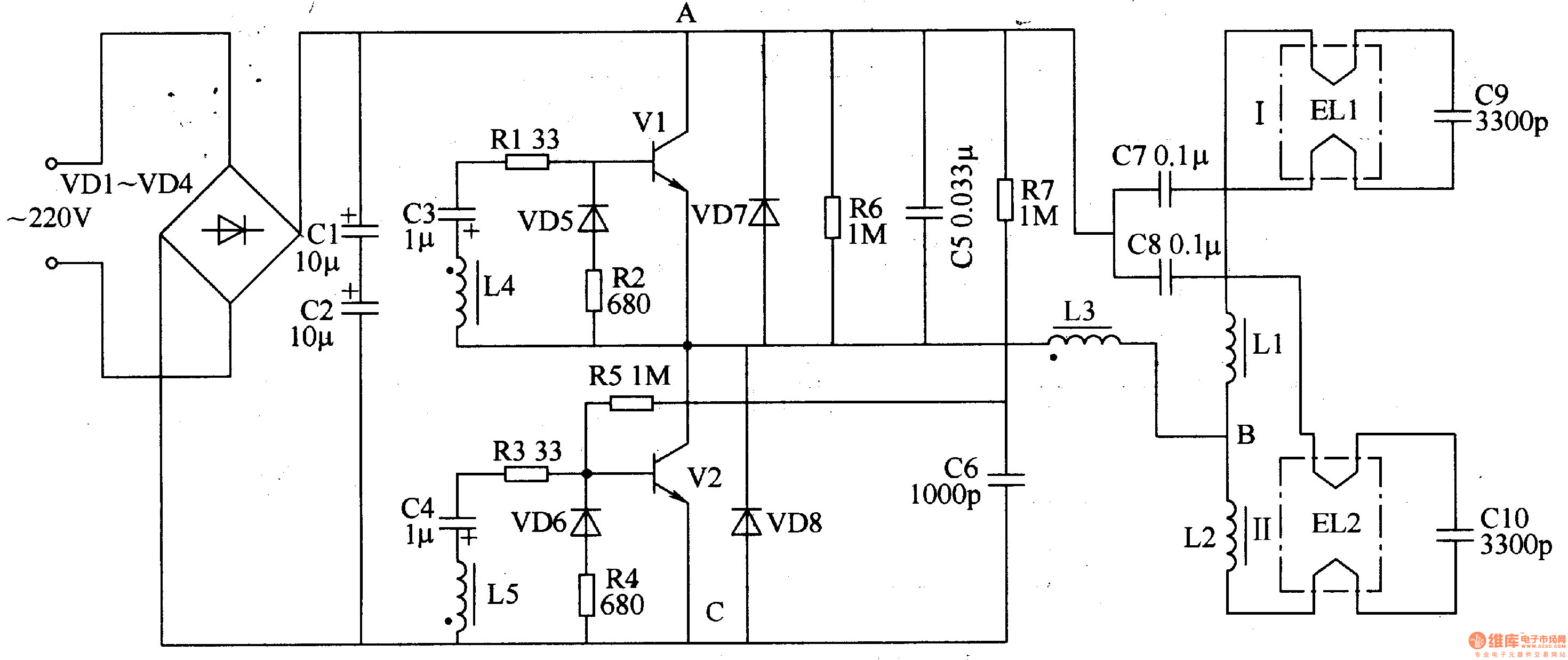
The electronic ballast circuit for fluorescent lamps comprises a rectifier filter circuit, a high-frequency oscillator circuit, and an output circuit, as illustrated in Figure 3-202. The rectifier filter circuit consists of rectifier diodes VD1-VD4 and filter capacitors C1 and...
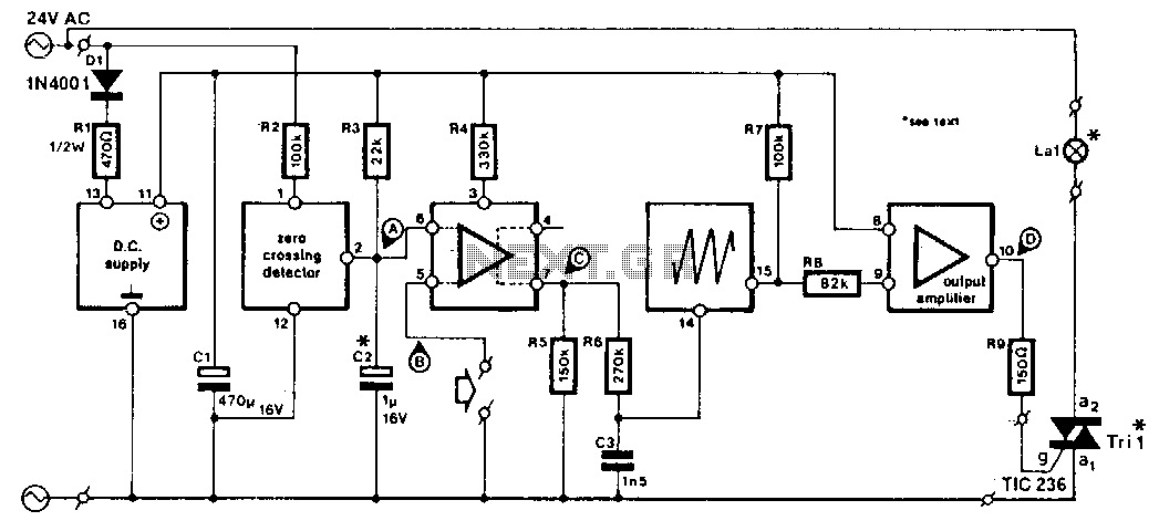
This circuit is designed for integration into slide projectors that lack a dimmer functionality, specifically for use with 24-V AC fed halogen lamps. With minor modifications, it can also be adapted for dimming 12-V halogen lamps, although it is...