
light dimmer circuit
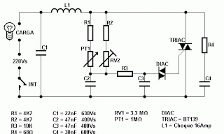
This circuit is designed for dimming incandescent or resistive load light bulbs by controlling the power delivered to them through phase-cutting techniques. The primary component, the triac, serves as a switch that allows current to flow only during specific portions of the AC waveform. The adjustment mechanism incorporates a variable resistor (PT1) and potentiometer (RV2) to finely tune the light output. The delay introduced by capacitors C1 and C2 is critical for determining the phase angle at which the triac is triggered, thus enabling smooth brightness transitions.
The use of a DIAC ensures that the triac remains off until a specific voltage threshold is reached, providing a controlled and predictable switching action. The RC snubber circuit (R4 and C4) is essential for mitigating voltage spikes that could inadvertently trigger the triac, ensuring reliability and longevity of the circuit. This design is particularly suitable for applications requiring adjustable lighting levels, such as in residential or commercial settings, where energy efficiency and user comfort are priorities. Proper thermal management of the triac is crucial, necessitating the use of a heat sink to dissipate heat generated during operation. The overall architecture of this circuit exemplifies a balance between functionality and safety, making it a valuable addition to any lighting control system.This circuit operates at potentially lethal 220V AC mains voltage. The circuit should be built and used only by people who know hot to safely work with such dangerous voltages and how to built the circuit so that it is safe to use. Solid-state light dimmers work by varying the "duty cycle" (on/off time) of the full AC voltage that is appl
ied to the lights being controlled. For example, if the voltage is applied for only half of each AC cycle, the light bulb will appear to be much less bright than when it get the full AC voltage, because it get`s less power to heat the filament. Solid-state dimmers use the brightness knob setting to determine at what point in each voltage cycle to switch the light on and off.
The exact time when the triac is triggered relative to the zero crossings of the AC power is used to determine the power level to the light bulb. When the the triac is triggered it keeps conducting until the current passing though it goes to zero (exactly at the next zero crossing if the load is purely resistive, like light bulb).
By changing the phase at which you trigger the triac you change the duty cycle and therefore the brightness of the light. The circuit contains a variable resistance that consists of R1 + PT1 in paralle with R2 + RV2. This variable resistance together with capacitors C1 and C2 form a delay from the mains zero crossing to the firing point of the diac.
DIAC is a bidirectional trigger diode that conducts current only after its breakdown voltage (typically around 30V) has been exceeded momentarily. The larger the variable resistance feeding the capacitors, the longer it takes for the voltage across the capacitor to rise to the point where the DIAC fires turning on the triac TH1.
The circuit is calibated in such way that first PT1 is turned to highest resistance values. The value of RV2 is turned in such position that the desired minumum brightness of the light bulb is reached. After this calibration the PT1 can be used to freely control the light bulb brightness at the desired control range form the maximum brightness to set minumum.
Capacitor C1 and inductor L1 make a simple radio frequency interference filter. Without it the circuit would generate quite much interference because firing of the triac in the middle of the AC phase causes fast rising current surges. The triac BT139 used in the circuit is rated for 16A continuous current when properly cooled with a large heat sink.
The maximum current is less with less cooling. The components R4 and C4 for a RC nubber network that protects TRIAC from spurious triggering. 🔗 External reference
Related Circuits
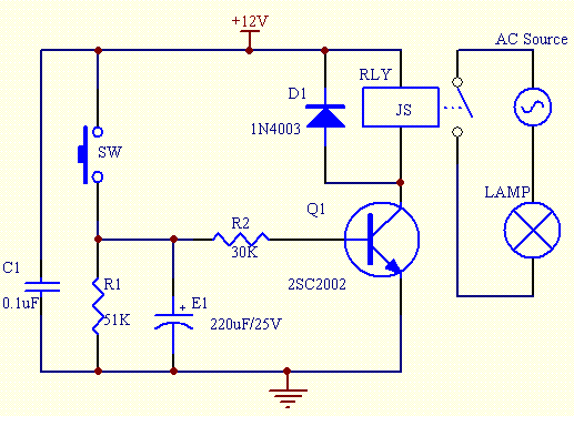
This simple electronics timing light uses an RC circuit as a delay-off timer to control an incandescent lamp via a relay. The described timing light circuit employs a resistor-capacitor (RC) network to create a time delay that governs the operation...
If you have ever used a 12V flasher relay system, typically a mechanical type, for general automotive applications, today we will attempt to build a 12V flasher relay circuit. The 12V flasher relay circuit is a crucial component in automotive...
Typical segment display LEDs consume around 25 mA for each segment and should be limited to this current with resistors. For a six-digit display to be current limited, at least 42 series resistors are needed. The brightness of the...
Recently, there has been a focus on Jeep repair due to an issue preventing the XJ from starting. However, during this time, progress has been made on initial modulation tests of the PT2399 circuit, resolving many bugs. The main...
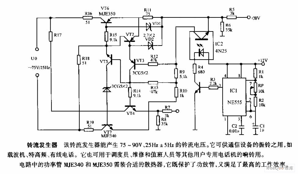
The ring current generator can produce a ringing current voltage of 75-90V and 25Hz ± 5Hz. It is suitable for use in vibrating rings in communication devices, such as carriers, ultrahigh frequency systems, and wire telephones. Additionally, it can...
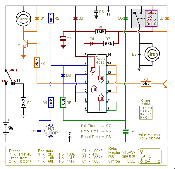
This is an improved version of the basic Garage/Shed Alarm. The Entry and Exit delays have been extended to approximately 30 seconds, and a timed Siren cut-off along with an automatic reset feature has been added. Additionally, the LED...