
Lamp Dimmer / Motor Speed Control
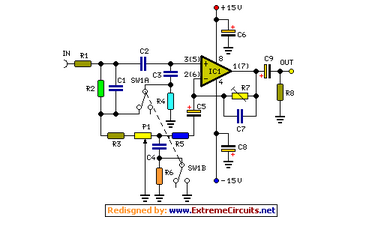
The described circuit functions as a dimmer for incandescent lamps by utilizing a pair of 2N2222 bipolar junction transistors (BJTs) to replicate the behavior of a diac. The circuit is designed to control the power delivered to the lamp by varying the phase angle of the AC supply voltage. A key component in this design is the 250K potentiometer, which adjusts the charging time of the capacitors involved in the triggering mechanism.
As the AC voltage rises in each half cycle, the .068 µF capacitor charges through the 250K potentiometer. This capacitor plays a crucial role in determining the timing of the trigger pulse sent to the triac. Once the voltage across the .068 µF capacitor reaches a certain threshold, it begins to charge the .047 µF capacitor through the 68K resistor. The charging process continues until the voltage across the .047 µF capacitor reaches approximately 10 volts. At this point, one of the 2N2222 transistors switches from a non-conducting state to a low-resistance state, effectively connecting the .047 µF capacitor to the gate of the triac. This triggers the triac, allowing current to flow through the lamp for the remainder of the half cycle.
The operation of the dimmer is contingent upon the phase angle at which the triac is triggered, which is directly influenced by the resistance set on the potentiometer. Lowering the resistance allows the capacitor to charge more quickly, resulting in an earlier trigger pulse and, consequently, a longer duration of current flow through the lamp. This phase control enables the user to adjust the brightness of the lamp, achieving a variable duty cycle.
The use of two transistors in this configuration allows for the handling of both half cycles of the AC waveform, with each transistor responsible for triggering the triac during its respective half cycle. This method of using BJTs instead of a diac illustrates the versatility of transistors in applications typically reserved for specialized components. The circuit, while not optimized for high performance, serves as an educational demonstration of the principles of phase control in AC circuits and the operation of triacs. Caution is advised when working with AC mains voltage, and proper safety measures should always be observed.The diac is a common component used to trigger triacs. The construction of a diac is similar to that with a transistor, but with both junctions doped to similar levels so that the two junctions' revers break down characteristics are similar. This is a fun project to demonstrate the use of a pair of bipolar transistors operating in their negative resistance region to simulate a diac triggering a triac in an incandescent lamp dimmer.
The circuit is not optimized for performance -it is only intended to demonstrate the principle. The waveforms above should look like the last 90 degrees of the positive and negative half cycles of the AC line, but this is what the hot AC line actually looks like in my neighborhood. No wonder some jurisdictions require appliances to meet power factor requirements. By the way, be careful to consider your scope probe's voltage rating when probing the AC mains, even through an isolation transformer, since the peak voltage may be higher than the probe or scope's rated voltage.
I used a X100 probe rated at 1kV. I'm not going to spend much space on this because this is not a beginners' project and the operation of this kind of lamp dimmer is covered elsewhere on the web. The photograph above shows the voltage across an incandescent light bulb that is being driven by the triac dimmer circuit.
Notice that the lamp is only being driven 1/2 the time of each half of the power line cycle. That means that the lamp only gets half the average power. The fraction of each power line half cycle applied to the lamp is determined by the time within the half cycle that the triac, which switches the voltage across the lamp, turns on. When the voltage goes to zero, the triac turns off and waits for the next trigger pulse. That's how this kind of dimmer works. But varying the phase within each half cycle at which the triac turns on. Within each half cycle, the power line voltage charges the .068 uf capacitor through the 250K pot. The voltage across the .068 uf capacitor further charges the .047 uf capacitor through the 68k resistor, until the voltage across the .047 uf capacitor reaches about 10 volts.
When the voltage across the .047 uf capacitor reaches about 10 volts, one of the two 2N2222 transistors abruptly switches from a non conducting state to a very low resistance. Being a low resistance, it places the .047 uf capacitor across the trigger terminal and main terminal 1 of the triac, turning the triac on for the rest of the half power line cycle.
The lower the resistance of the 250k pot (used as a rheostat), the earlier in the cycle the voltage across the .047 uf capacitor reaches the triggering voltage. Varying the resistance of the 250k pot varies the phase of the trigger pulse with respect to the phase of the power line, thus achieving a variation in the average on time of the triac, which results in a varying duty cycle across the lamp.
Often, the function of the trigger, that provided by the 2N2222 transistors, is provided by a diac, a specially designed semiconductor with a structure similar to that of a transistor, that abruptly changes from not conducting to conducting when the voltage across it exceeds some specific value. I wanted to do this with transistors to show that, in a pinch at least, transistors can be used for this function.
Two transistors were used in place of the one diac so that one transistor would break down on one half cycle and the other transistor would break down on the other half cycle. The break-downs occurs in the reverse biased emitter-base junction, which is a much lower voltage than the reverse biased collector to base junction.
In this circuit, the 2N2222's provided pulses of about 1 microsecond with amplitudes of 100 to 200 milliamps to the gate of the triac. 🔗 External reference
Related Circuits
A fluorescent starter bimetal can be utilized as a temperature sensing element for thermostatic control. This component consists of a double metal sheet designed for temperature sensing, resulting in a simple circuit that is easy to manufacture, although it...
Simple add-on module, Switchable "Control-flat" option. In order to obtain good audio reproduction at different listening levels, a different tone control... The described module is a straightforward add-on designed to enhance audio reproduction across various listening levels. The "Control-flat" option...
There is no PCB since there are no components to mount on one. The object was to create a source of ultraviolet light as fast as possible. The UV tubes I bought from a lighting shop for use with...
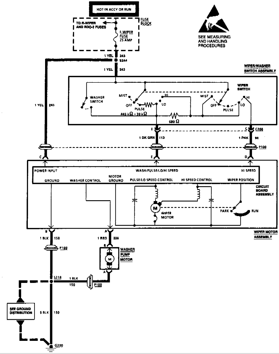
A 1994 Pontiac Transport has an issue where the front wipers only operate on the high setting. A suggestion has been made that a wiper motor replacement may be necessary, while another opinion indicates that the wiper pulse module...
A new user is seeking to share information about their experiences on this platform. The user expresses a desire to communicate and engage with the community regarding their experiences. This indicates an interest in exchanging knowledge and possibly seeking assistance...
The initial program will sweep the servomotor from counterclockwise (CCW) to clockwise (CW) and then back again. The program is designed to illustrate the principles of controlling a servo using the PIC Basic language. The schematic is referenced in...