
Servomotor Control Program

To implement the described servo control program, a basic schematic will include the following components: a PIC microcontroller, a power supply, a servomotor, and the necessary connections to facilitate pulse width modulation (PWM). The PIC microcontroller will generate the PWM signals required to control the servomotor's position.
The power supply should be capable of delivering sufficient voltage and current to the servomotor, typically around 5-6 volts for standard servos. The servomotor will be connected to one of the PWM-capable output pins of the PIC microcontroller. The control signal will be sent as a series of pulses, where the duration of each pulse determines the position of the servo.
The variable `pw` will be set in the program to control the pulse width. The initial value of 100 corresponds to a pulse width that positions the servo at -45 degrees. As the program executes, `pw` will be incremented, adjusting the pulse width and moving the servo toward the 45-degree position. Once the maximum pulse width is reached (200), the program will reverse the process, decrementing `pw` back to the minimum value.
For users wishing to extend the servo's range to a full 180 degrees, careful adjustments to the pulse width parameters will be necessary. The adjustments should be made with consideration for the specific requirements of the servomotor being used, ensuring that the pulse width values do not exceed the operational limits of the motor. Proper calibration may involve measuring the exact pulse widths needed for the desired range of motion, taking into account the unique characteristics of the selected servomotor.
In summary, the described program and schematic provide a straightforward approach to servo control using a PIC microcontroller, while also emphasizing the importance of understanding the specifications and limitations of the servomotor to ensure reliable and effective operation.In our first program, we will simply sweep the servomotor from CCW to CW and then sweep back. The program will be kept simple as to demonstrate the priniciples of controlling a servo with a the PIC Basic language. The schematic can be seen in figure 2 (below). The variable pw controls the pulsewidth, and is started at 100 (extreme left, -45 degrees). The program sends the pulse out to the servo, and then is increased by a value of 1 until it reaches 200 (extreme right, 45 degrees), at which point it will reverese the rotation. If desired, we could extend the rotation of the servomotor to a full 180 degrees (-90 to 90 degrees) rotation by decreasing the minimum pulsewidth to below 1 ms and increasing the maximum pulsewidth to over 2 ms.
This can be accomplished with our previous program by modifying the occurances of 100 and 200 to your desired minimum and maximum pulsewidths, respectivly. However, a note of caution: the pulsewidth required for servos varies from brand to brand. One motor may require a 2. 8 ms pulsewidth for maximum rotation, while another may only need 2. 4 ms. Furthermore, servomotors have end stops that limit its rotation. If you send the motor a pulsewidth that is beyond the end stops, the motor will keep trying to turn. A motor in this stalled condition not only draws more current, but also puts wear on the internal gears, shortening the lifespan of the motor.
🔗 External reference
Related Circuits
A radio remote control system utilizing DTMF (Dual-Tone Multi-Frequency) technology is presented. This circuit allows for the control of various electrical appliances through radio frequency signals. The described radio remote control system employs DTMF tones, which are generated by a...
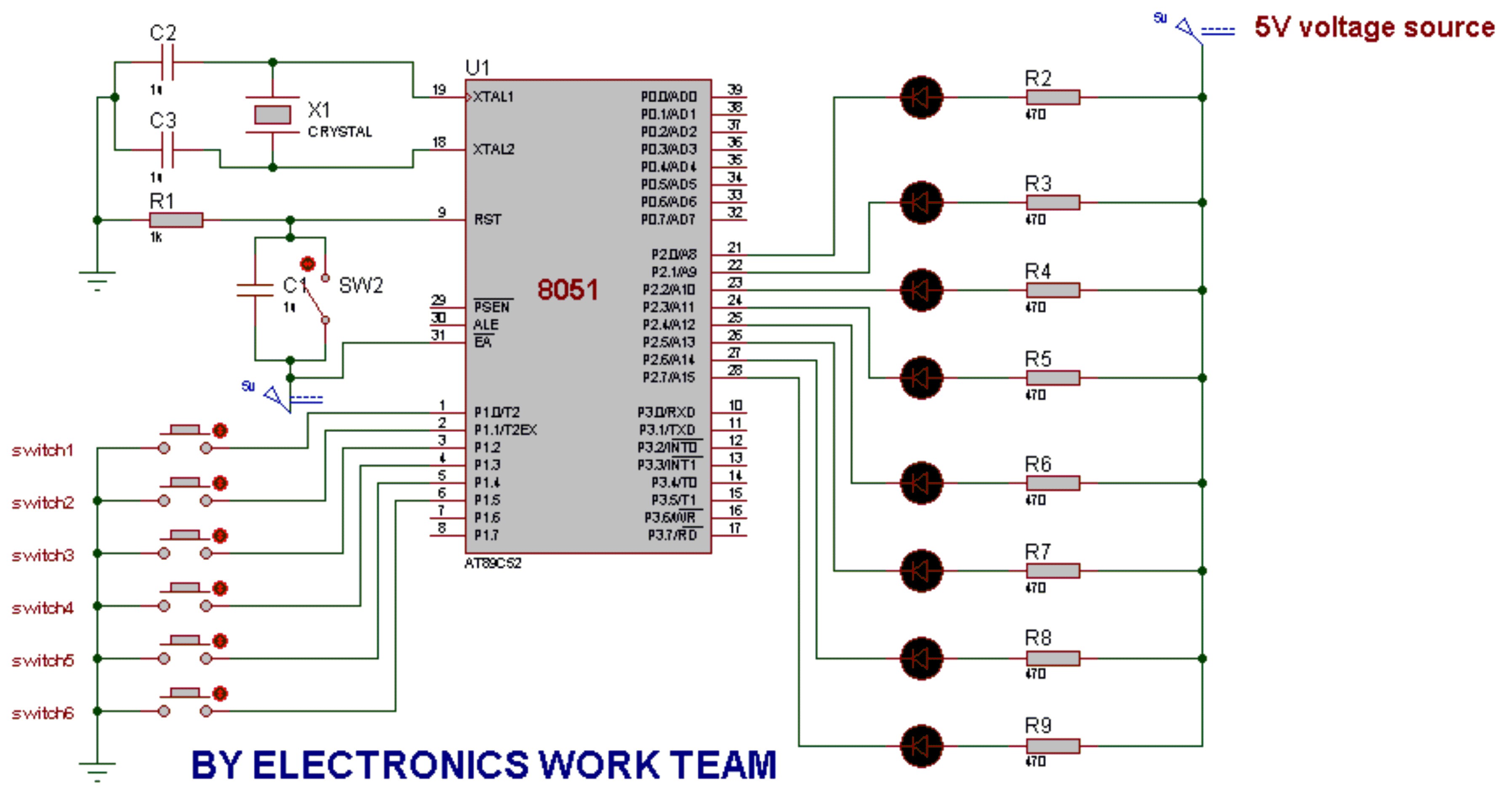
This post discusses the fundamental operation of the 8051 microcontroller using LEDs. The LEDs are connected to the P2 port, while six switches are connected to the P1 port of the 8051. By pressing various switches, the LEDs will...
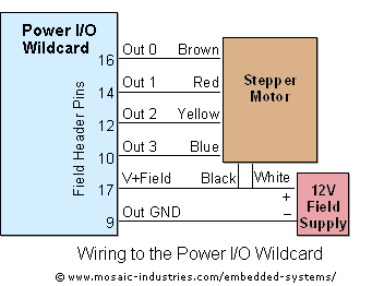
For optimal efficiency, set MAX_STEPPERS to the number of stepper motors being controlled, with a maximum limit of four. Motors are identified by indices 0, 1, 2, and 3. On the QCard, there is a trade-off between the number...

This circuit operates effectively across a broad frequency spectrum. XTAL 1 serves as a fundamental-frequency crystal. Tl and CI are adjusted to match the input frequency. This circuit can be utilized as a straightforward shortwave converter for AM radios,...
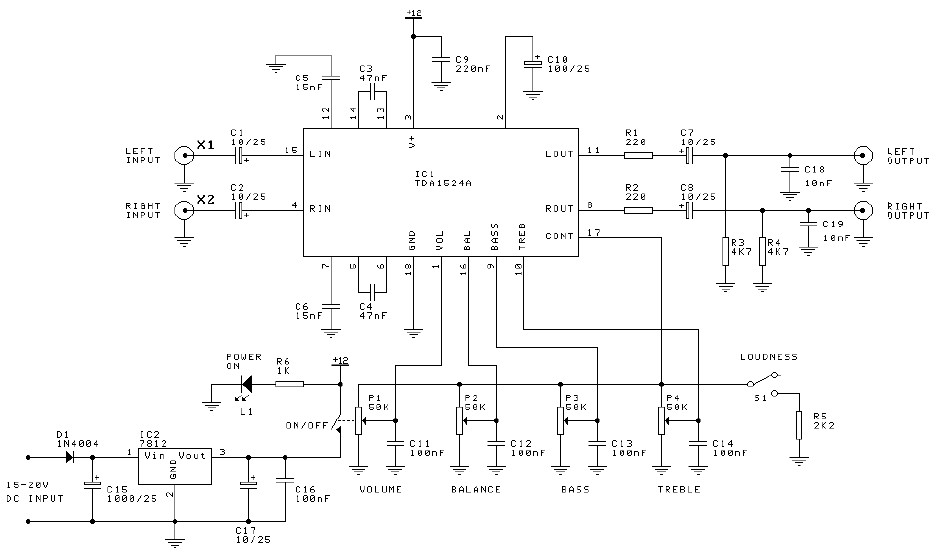
Preamplifier and tone control circuit based on the TDA1524A. The tone control circuit module is included in this preamplifier circuit, allowing for direct connection of the output channels to a stereo power audio amplifier circuit. This RIAA stereo preamplifier...
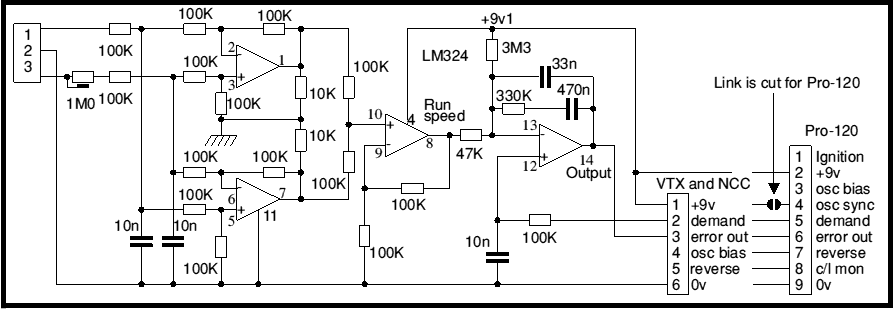
Most battery motor speed controllers are under manual control and the operator automatically adjusts speed to match demand. Under these conditions closed loop motor speed control is an unnecessary expense. However, when it is required, a tachogenerator can easily...