
Lamp Dimmers

The circuit described is indicative of a basic electronic design that lacks certain filtering components, notably a choke, which is essential for reducing electromagnetic interference. The absence of a choke can lead to substantial RFI, which may affect nearby electronic devices and communication systems. The design's reliance on house wiring to limit di/dt suggests that it is intended to operate within typical residential electrical parameters, utilizing the inherent inductance of the wiring to mitigate rapid changes in current.
The mention of hysteresis at dim settings indicates that the circuit may employ a feedback mechanism that stabilizes the output brightness against fluctuations in input voltage or load conditions. This hysteresis can be beneficial in preventing flickering or instability at lower brightness levels but may also introduce undesirable effects if the feedback is not properly designed.
Furthermore, the statement about the quality of consumer products implies that this design may be a low-cost solution that sacrifices performance for affordability. Such designs may be prevalent in low-end consumer electronics where cost constraints take precedence over performance optimization. The implications of this can lead to a user experience that is less than satisfactory, particularly in environments sensitive to RFI.
In summary, the circuit's design, while economical, may not meet the expectations of users looking for high-quality performance, especially in applications where RFI is a concern. Proper circuit design would typically include additional components such as chokes, capacitors, and possibly shielding to enhance performance and reduce interference.This must generate an awfull lot of RFI without a choke! The house wiring supplies the di/dt limiting. This is a CHEAP design which exhibits hysterisys at dim settings. Not everything made and sold to the public is top notch. 🔗 External reference
Related Circuits
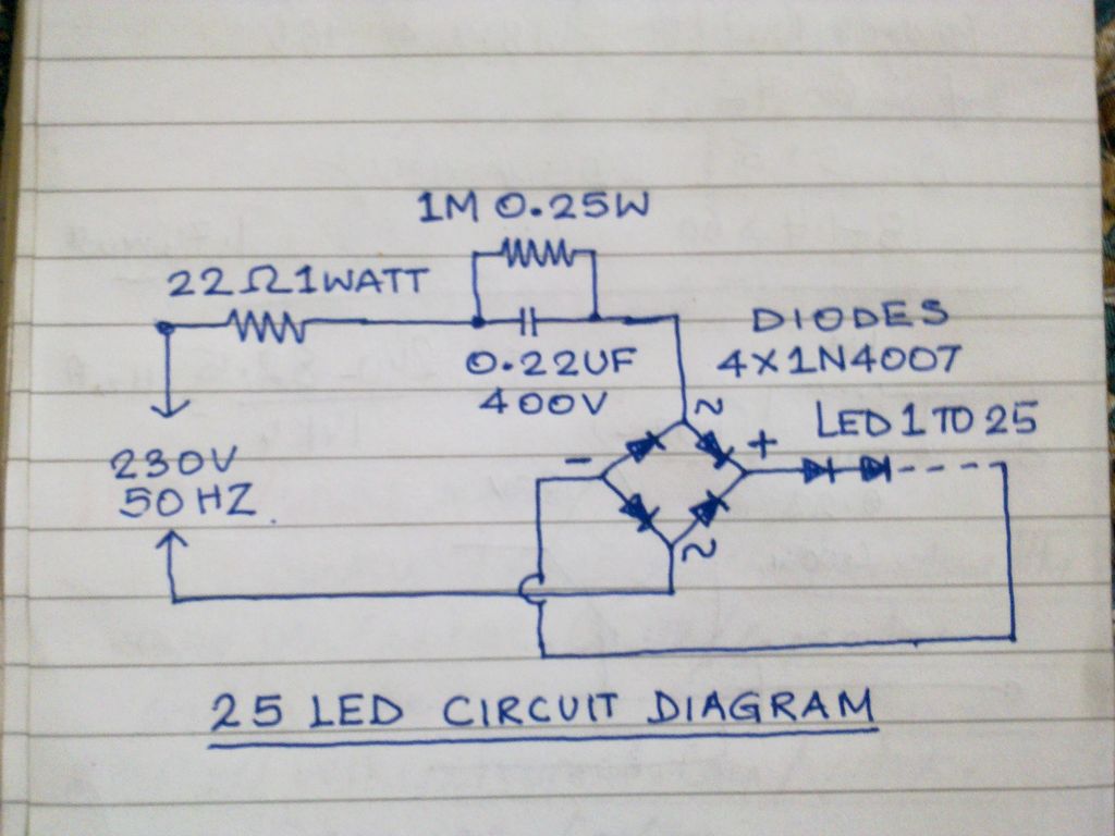
This circuit operates 25 LEDs powered by a mains supply of 230V. A fluorescent lamp adapter was acquired from a scrap dealer for ease of disassembly. The circuit consists of a series of 25 light-emitting diodes (LEDs) arranged to operate...

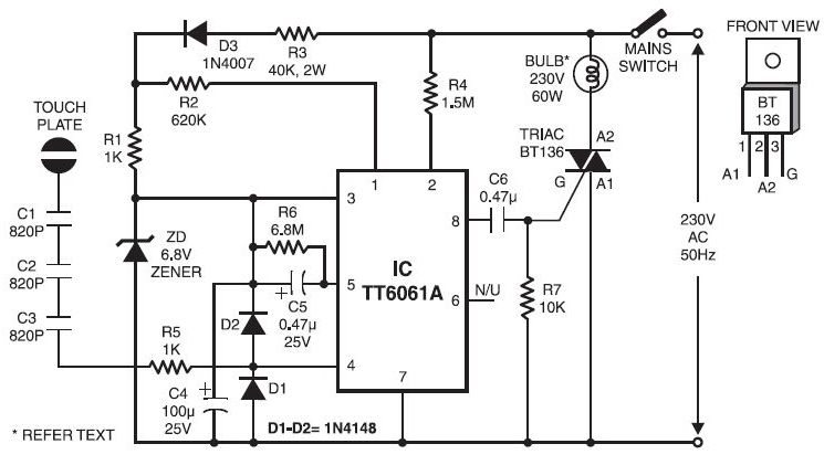
Without a heatsink, Triac Q1 can handle a load of up to a 400-watt lamp. The neon lamp does not trigger the gate until it begins conducting, resulting in the lamp turning on with medium brilliance. Subsequently, the lamp...
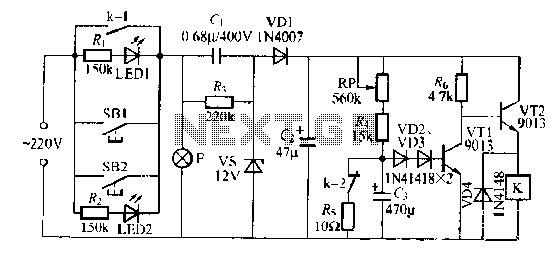
The lamp relay delay circuit is illustrated in Figure 7. Components S131 and SB2 are light buttons mounted in different locations. The lamp can operate with F. LEDs (LED1 and LED2) should be installed in SB1 and SB2 to...
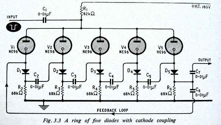
The above shows a home-built digital clock that utilizes Nixie tubes for display. Unlike most contemporary Nixie clocks, this design does not employ transistors or integrated circuits for driving the tubes. Instead, the driving logic is constructed using neon...
Typically, when a car door is closed, the dome light turns off immediately. This circuit allows the dome light to gradually fade in brightness before eventually turning off. An electronic transformer dims halogen lamps and is a straightforward device...
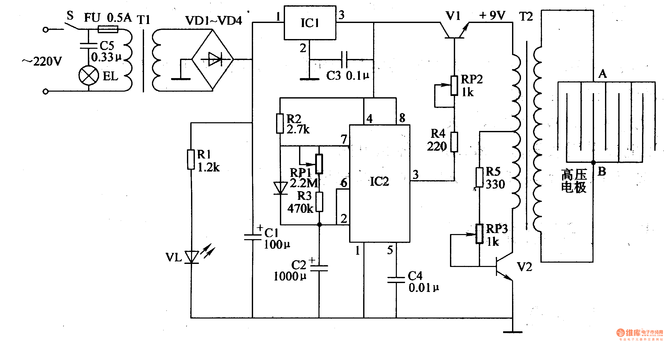
Working Principle: The circuit, as illustrated in figure 4-187, is composed of three main components: the power circuit, the pulse oscillator, and the high voltage generator. The power circuit includes components S, FU, TI, VD1-VD4, C1, C3, IC1, R1,...