
Lamp relay delay circuit
The lamp relay delay circuit operates based on a combination of resistive and capacitive components that establish a time delay for the activation and deactivation of the lamp. The circuit's design incorporates a step-down regulator that converts higher voltage inputs into a stable 12V DC output, essential for the reliable operation of the relay and associated components. The use of LEDs for switch position indication enhances user interaction by providing visual feedback regarding the circuit's state.
The relay employed in this design, the JRX-13F, is particularly suited for applications requiring compact size and reliable operation. Its two changeover contacts allow for versatile circuit configurations, enabling the design to accommodate various load requirements. The interaction between the relay and the capacitors is critical; as the capacitors charge, they create a delay in the relay's response, allowing for controlled operation of the lamp. The adjustment of the resistor RP allows for fine-tuning of the delay time, providing flexibility in the circuit's performance based on specific application needs.
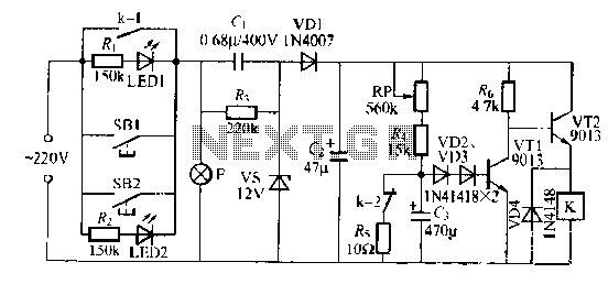
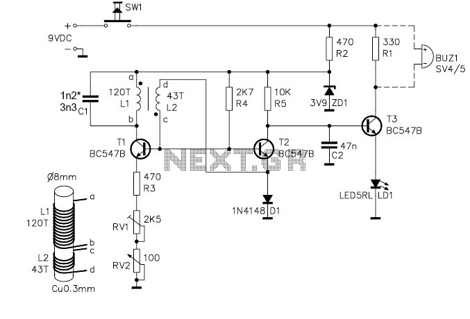
Overall, this circuit exemplifies a practical application of electronic components to achieve a desired functionality, demonstrating the principles of relay operation, voltage regulation, and delay mechanisms effectively.Lamp relay delay circuit shown in Figure 7], S131, SB2 are lights button mounted anti-machi not a different place, the lamp can operate F. LEDs LEDl, LFr) 2 should be installed in SB1 and SB2 at the "Peter asked in switch position indication easy to use.
When the lights required, just press the SB1, SB7 any one towel a lamp E on the light-emitting. LEDI, LED2 goes off. and the same time at both ends of the lamp post .1 NIE galvanic suffer through (J, c ,, VS, VD1 and other simple electrical composed of step-down regulator rectifier circuit, in (Both ends of the steady output of about 1 2V given DC voltage. Since the feet. RP resistance is much less than ten Torr, VT1 off, VT2 conduction, so the relay K station, station electric shock kl closing station, the circuit self-locking.
At the same time, jump off contact k2 Since two capacitors G J terminal voltage can not mutation, VTI remains off state so that a lamp F may continue to emit light. then, 12V DC by the RP, R to allow electricity to make (1 Galvanic callosum constantly J high, when rose 3 0 65V just, VD2, VD3 and are conduction VT1, VT2 off energized relay K release, its contact kl, k2 reset, turn off the lamp F, called with LED1, LED2 and light indication switch position.
trimming pruning when the resistor RP coup lights can delay l Division, K called using JRX-13F, DClZV other small type electromagnetic relay which has two changeover contacts, can be full enough Bong circuit requirements.
Related Circuits
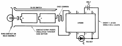
The schematic presented below illustrates the Flashlight Finder circuit diagram utilizing the LM3909, a monolithic oscillator specifically designed for flashing Light Emitting Diodes (LEDs). The Flashlight Finder circuit employs the LM3909 integrated circuit, which is capable of generating a series...
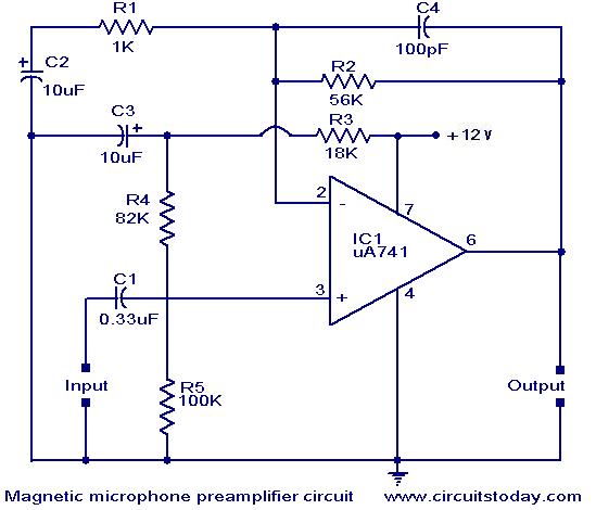
A preamplifier for magnetic pickups of record players is presented. The uA 741 is utilized as an AC-coupled non-inverting amplifier operating on a single supply. The amplifier gain is determined by the feedback components, where C2 manages the low-frequency...
The sunset lamp activates at full brightness and gradually dims over a duration of 1.5 hours, remaining off until the power is reset. The sunset lamp circuit is designed to simulate the natural fading of sunlight, providing a calming effect...
The project demonstration has been successfully completed, with the only remaining task being the final project report due on June 15, which will be integrated with a conference paper. This update marks the last entry in the electronic notebook,...
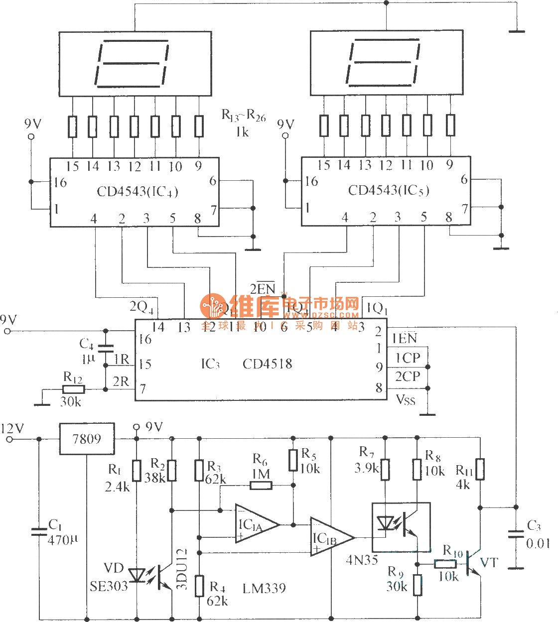
The circuit includes an optical input circuit (VD, 3DU12), a pulse forming circuit (IC1A, IC1B functioning as a voltage comparator; optical coupler; transistor switching circuit), and a counting and display circuit. The circuit architecture consists of several key components that...
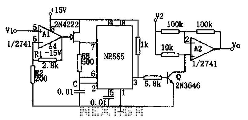
The circuit depicted in the figure consists of a voltage-frequency converter and an amplitude modulator. The input voltage V1, processed by operational amplifier A1, controls the FET 2N4222's internal resistance, which in turn alters the oscillation frequency of the...
Warning: include(partials/cookie-banner.php): Failed to open stream: Permission denied in /var/www/html/nextgr/view-circuit.php on line 713
Warning: include(): Failed opening 'partials/cookie-banner.php' for inclusion (include_path='.:/usr/share/php') in /var/www/html/nextgr/view-circuit.php on line 713