
Laptop Power Supply for Car Schematic Diagram

The adapter utilizes the LM3524 chip, a high-frequency switching DC-DC converter capable of handling output currents up to 200mA. In this configuration, the output current is increased to 3.5-4A via powerful transistor switches (VT1 and VT2). The circuit functions as follows: the vehicle network voltage is fed into the supply circuit and output circuits through a key fuse (F1) and a low-resistance wire resistor (R6), which mitigates the generator's startup and protects against overload. The current consumption of the chip D1 is determined by the voltage across R6, which connects to the overload protection inputs (pins 4 and 5 of D1). As the load current increases, so does the voltage across R6, reflecting the actual current drawn from the source.
The output transistors are configured in parallel with the D1 circuit (emitter terminals connected to pins 14 and 11, and collectors to outputs 12 and 13). A resistor (R10) is connected to the collectors of the output transistors, allowing pulse signals to be fed to the non-inverting inputs of transistors VT1 and VT2. Transistor VT1 functions as the pre-inverter, while VT2 is a powerful field-effect transistor with low on-resistance. The low impedance of the open channel in VT2 minimizes power dissipation, requiring minimal heat sinking; however, it is advisable to use a radiator plate for the output transistor, such as a vertical TV type 3 USTST (approximately 25x35mm in size).
To stabilize the output voltage, a comparator is employed with inputs connected to pins 1 and 2 of D1. Pin 2 receives a reference voltage from the internal regulator circuit (output from pin 16), while the output voltage is derived from the power supply output through a low divider (R3-R4-R5). The output voltage is adjustable based on the divider ratio and can be fine-tuned using a multi-turn trimmer resistor (R4), which is set to values between 15 and 22 volts for optimal performance.
When connecting this circuit to a vehicle's onboard network, strict attention to polarity is essential to avoid damage to the inverter. The ideal connection point is directly at the battery terminals to minimize interference. Furthermore, the converter housing should be adequately shielded to prevent electromagnetic interference, ensuring reliable operation of the laptop power supply circuit for automotive use.Laptops today are the what is called notebook computers, which now is becoming popular. Laptops can be brought into the bag making it suitable for business trips. And even as the home entertainment center laptop is more convenient, because it takes a little space. However, in my opinion, there is one very important which become shortcomings most laptops which powered by an electric voltage of 19V, making it impossible for them to direct the power to an integrated network vehicle (12-14V). It is very important, especially when laptop battery capacity is not more than two hours in active mode.
And what if you, at some object in the whole day want to process some data, but no other useful sources of electricity This is a description of the relatively simple psu laptop circuit adapter (laptop DC-DC converter), which increases the voltage-board vehicle network to 19V, needed to supply the laptop. And maintain this voltage stable. The adapter is based on chip LM3524, which is a high-frequency switching DC-DC converter with pumped inductance and output current up to 200mA, the output current which, in this scheme, will increased to 3.
5-4A using a powerful transistor switch (on transistors VT1 and VT2). Consider the circuit carefully. Voltage on-board vehicle network goes to supply circuit and output circuits D1 through key fuse F1 and low-resistance wire resistor R6, mitigating start the generator and the circuit operates in overload protection. Current consumption chip D1 determines the voltage at R6, enter the inputs of overload switching Conclusions 4 and 5 D1.
The voltage on the R6 increases with what greater than the load current (and actual current consumption from the source). A pair of output transistors connected in parallel circuits D1 (emitter terminals 14 and 11, collectors the outputs of 12 and 13).
Loaded with collectors of output transistors a resistor R10. With this resistor pulses are fed to the non-inverting switch on transistors VT1 and VT2. Transistor VT1 is the pre-inverter, and s as the output transistor VT2 uses a powerful field-effect transistor with a small key resistance of the open channel. Due to the low impedance of the open channel, in spite of considerable current, power dissipated in it is small, and almost no heat sink required.
Exclusively to ensure it is installed on the radiator plate output transistor Vertical TV type 3 USTST (plate size of approximately 25h35mm). In order to stabilize the output voltage using a comparator inputs are, pins 1 and 2 D1. On pin 2 through a divider R1-R2 is fed from the internal reference voltage regulator circuit (output of the stabilizer, output 16).
At the output a voltage is applied from the output of the power supply, low divider R3-R4-R5. The value of the output voltage depends on the ratio of the divider apart, and set trimmer R4 (in fact, ranging from 15 to 22 volts). It is desirable that the resistor R4 was multi-turn so its installation is more accurate and more stable.
The circuit relatively simple circuit adapter (DC-DC converter), which increases the voltage-board vehicle network to 19V, needed to supply the laptop. And maintain this voltage stable. The adapter is based on chip LM3524, which is a high-frequency switching DC-DC converter with pumped inductance and output current up to 200mA, the output current which, in this scheme, will increased to 3.
5-4A using a powerful transistor switch (on transistors VT1 and VT2). When connected to a vehicle on-board network, you must strictly observe polarity. Otherwise, the inverter fails. Optimally Connect directly to battery terminals. In this case it will be a minimum of interference. Converter housing must be shielded. You are reading the Circuits of Laptop Power Supply for Car And this circuit permalink url it is 🔗 External reference
Related Circuits

A simple yet effective circuit to generate a POTS-compatible ringing voltage can be constructed using National Semiconductor's LM4871 audio amplifier IC along with a dozen passive components. This circuit produces a sine-wave output of 1 W at approximately 70...
This is a straightforward, cost-effective Hi-Fi quality power amplifier. It can be constructed in five different configurations, as indicated in the table, ranging from 20 W to 80 W RMS. This Hi-Fi quality power amplifier is designed to deliver high...
Measure the voltage across the 1k resistor connected to the input stage and Vcc. The DC voltage should be approximately 2 volts, or 2 mA of current flowing through this resistor. For instance, if Vcc is at 24 volts,...
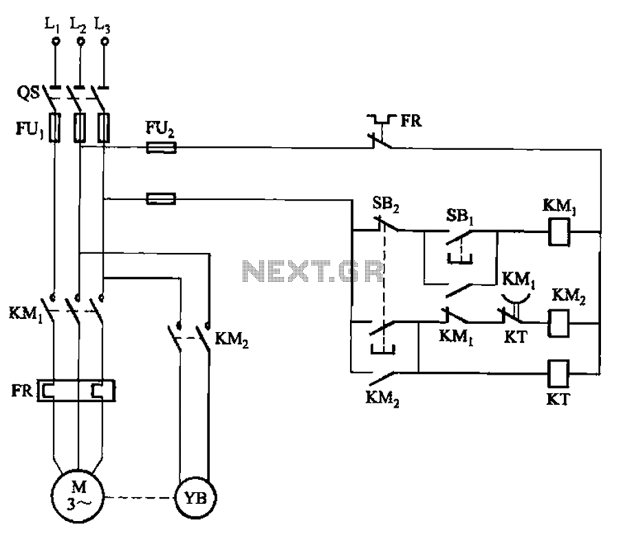
The circuit illustrated in Figure 3-123 operates as follows: When the stop button SBz is pressed, contact KMi releases, cutting off power to the motor. Simultaneously, KMz is activated, engaging the electromagnetic brake YB to hold the motor in...
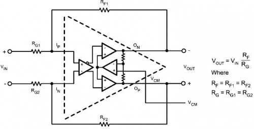
This circuit functions to provide balanced, low distortion amplification and level shifting for wide bandwidth differential signals. It utilizes the LMH6552 integrated circuit (IC) along with resistors. The LMH6552 is a high-speed, low-distortion amplifier designed for differential signal processing. It...
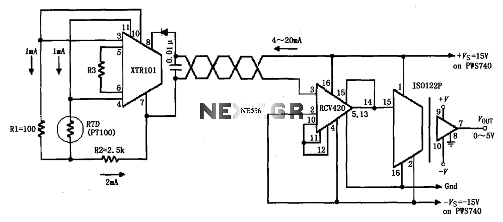
The circuit comprises an isolated RTD loop current configuration utilizing the XTR101 for transmitting loop current and the RCV420 for receiving it. The instrumentation amplifier detects changes in temperature via a resistance temperature detector (RTD), converting these changes into...