
Audio Power Amplifier
To execute the testing procedure effectively, it is crucial to ensure that the circuit is configured correctly before applying power. The 1k resistor serves as a current-limiting component, allowing for safe measurement of the voltage drop across it. The anticipated voltage of approximately 2 volts indicates that the circuit is functioning within expected parameters, and the current should be closely monitored to prevent exceeding the safe operating limits of the output transistors.
When adjusting the variable resistor, it is advisable to proceed slowly to avoid sudden changes in current that could lead to damage. The oscilloscope serves as a vital tool for visualizing the output waveform, and the absence of the 330 pF capacitor during this test is critical to eliminate potential phase shifts that could affect the results. A clean 20 kHz square wave with minimal ringing indicates proper amplifier performance, while oscillation suggests instability in the circuit that needs to be addressed.
After the initial testing phase, connecting the audio input and speaker should be done with caution. The volume should remain at a low setting initially to prevent any unexpected surges in current. Monitoring the current meter during this phase will help ensure that the amplifier operates within its safe limits. It is essential to adhere to the specified supply voltage requirements, as operating below +/- 30 volts can lead to suboptimal performance or damage. Finally, using a power supply capable of delivering at least 2 amps for an 8 ohm load is critical for achieving reliable high-volume output without risking damage to the amplifier.Measure voltage across the 1k resistor connected to the input stage and Vcc. The DC voltage should be about 2 volt, or 2 mA of current through this resistor. Eg, if Vcc is at 24 volts, the side of this resistor connected to the 2N5210 transisor ought to be at about 22 volts. Turn the variable resistor slowly until the amplifer`s current consumption is approx 50 mA. Turn slowly and be careful. if you turn too far you could damage the output transistors. Conect an oscilloscope to the output and apply a low amplitude 20 kHz square wave to the input. DO NOT connect any speakers during this test. This test should be done without the 330 pF capacitor installed. The amp should output a 20 kHz square wave with very little "ringing". It should not oscillate. Shut off the power, connect audio input and a speaker. Make sure the volume is turned all the way down. Apply power. watch current meter again and shut off the power immediately if the current jumps to something much higher than 50 mA. Slowly turn up the volume and see if the amp works. DO NOT turn it up very much. the amplifier should not be operated with a supply less than +/- 30 volts. It should never be used for high volume output without a power supply rated for at least 2 amps of current (8 ohm load).
After this initial test with +/- 24V at 200 mA (current limited) only a proper power supply should be used which can provide enough current. 🔗 External reference
Related Circuits
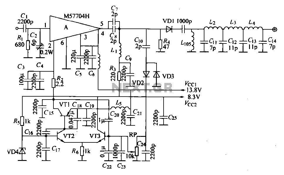
The FM radio transmitter is a high-frequency amplifier circuit that utilizes the Mitsubishi frequency set, specifically the M57704H discharge path. It operates within the frequency range of 457-458 MHz and has a transmission power of 5 watts. As illustrated...
.jpg)
The HID ballast circuit consists of a buck stage for regulating lamp current and power, a full-bridge output stage that generates a low-frequency (200Hz) AC square-wave voltage and current to drive the lamp, and an ignition circuit that produces...
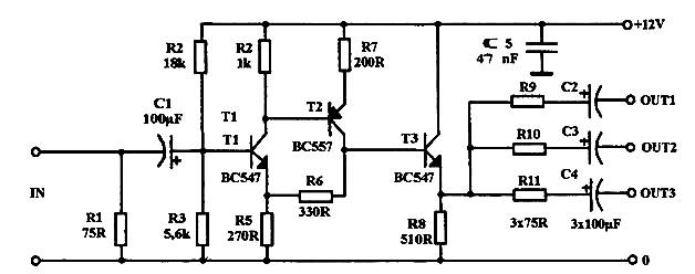
Video power amplifier circuit diagram. The circuit operates exclusively with AV compounds, where video and audio signals are transmitted separately. It is not suitable for connections involving "HF" antenna cables. Ensure that the video amplifier is included in the...
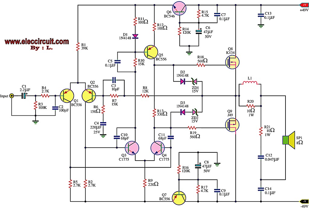
This is the first MOSFET power amplifier designed, featuring a comprehensive circuit. As a 60-watt power amplifier, it is adequate for typical usage. The 60-watt MOSFET power amplifier circuit is designed to deliver high efficiency and robust performance for audio...
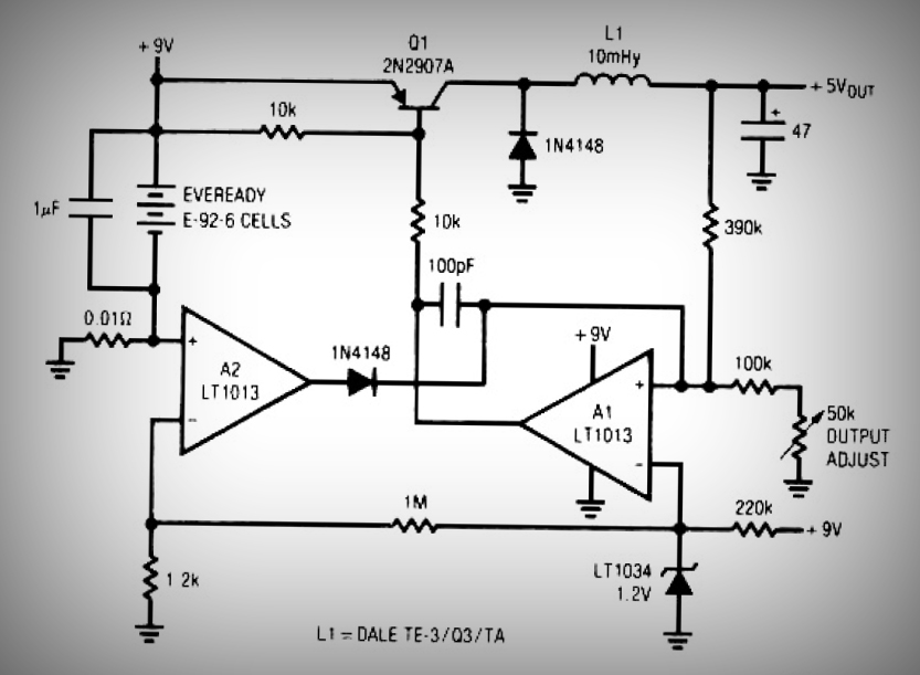
This circuit is a simple battery-powered switching regulator that provides a 5V output from a 9V source with 80% efficiency and a 50 mA output capability. When Q1 is on, its collector voltage increases, causing current to flow through...
Individuals seeking a distinctive gift for Christmas and New Year may find this project appealing. Certification of this project will undoubtedly create a preference for it. The project in question appears to be a creative endeavor aimed at providing a...