
Laser Controlled ON - OFF Switch
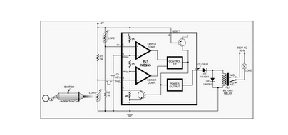
The circuit leverages the 555 timer IC, which is a versatile and widely used component in various electronic applications. The 555 timer can be configured in different modes, such as astable, monostable, and bistable. In this particular design, it is likely configured in astable mode, allowing it to function as an oscillator that generates a square wave output.
The basic components required for this circuit typically include the 555 timer IC, resistors, capacitors, and a power supply. The resistors set the charge and discharge times of the timing capacitor, which ultimately determines the frequency and duty cycle of the output waveform. The capacitor is charged and discharged through the resistors, creating the oscillating behavior characteristic of the astable configuration.
In practical applications, this circuit can be used for generating clock pulses, LED flashers, or tone generation in audio circuits. The output from the 555 timer can drive other components, such as transistors or relays, allowing for further control of larger loads or more complex functions.
The design's simplicity makes it an excellent project for educational purposes, as it provides insight into the operation of timers and oscillators in electronic circuits. Additionally, variations of this circuit can be explored by adjusting component values or configurations, leading to a deeper understanding of frequency modulation and timing applications in electronics.This circuit is built around a 555 timer using very few components. Since the circuit is very simple, even a novice can easily build it and use it as a co.. 🔗 External reference
Related Circuits
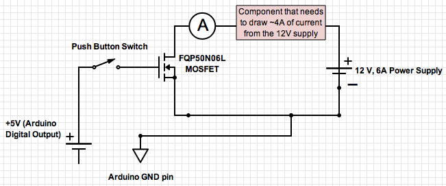
If the ground of the Arduino is disconnected from the negative terminal of the power supply, current flows through the MOSFET, even when the switch is not closed. In an electronic circuit involving an Arduino and a MOSFET, maintaining a...
Ultrasonic Switch. A circuit of a new type of remote control switch is described here. This circuit operates with inaudible sound waves. The ultrasonic switch operates by utilizing ultrasonic frequencies, which are sound waves above the range of human hearing...
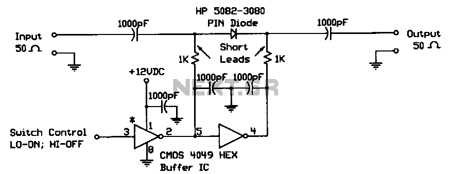
When the digital logic level at the control input is low, the PIN diode is forward-biased by the CMOS gates. The two 1-KΩ bias resistors limit this current to the PIN diode's safe forward current limit. In this state,...

The 2N4391 features a low ON resistance of 30 ohms and a high OFF impedance of less than 0 pF when in the off state. With appropriate layout and an optimal switch configuration, the stated performance can be easily...
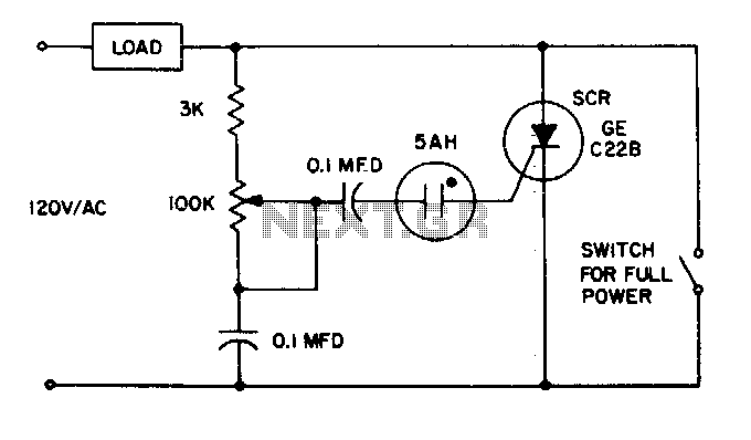
The 5AH will trigger when the voltage across the two 0 µF capacitors reaches the breakdown voltage of the lamp. Control can be obtained from full off to 95% of the half-wave RMS output voltage. Full power can be...
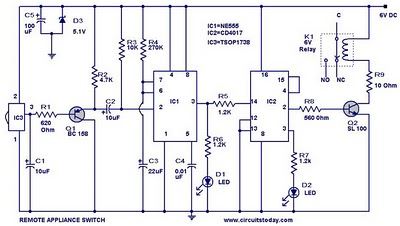
555 Timer TV Remote Controlled Home Appliance Circuit Diagram. Features: 555 timer IC to avoid fast switching. You can only switch the circuit. The 555 timer integrated circuit (IC) is a versatile component widely used in various electronic applications, including...
Warning: include(partials/cookie-banner.php): Failed to open stream: Permission denied in /var/www/html/nextgr/view-circuit.php on line 713
Warning: include(): Failed opening 'partials/cookie-banner.php' for inclusion (include_path='.:/usr/share/php') in /var/www/html/nextgr/view-circuit.php on line 713