
Ultrasonic Switch
The ultrasonic switch operates by utilizing ultrasonic frequencies, which are sound waves above the range of human hearing (typically above 20 kHz). The primary components of this circuit include an ultrasonic transmitter and receiver, which work in tandem to detect the presence of an object or person within a specific range.
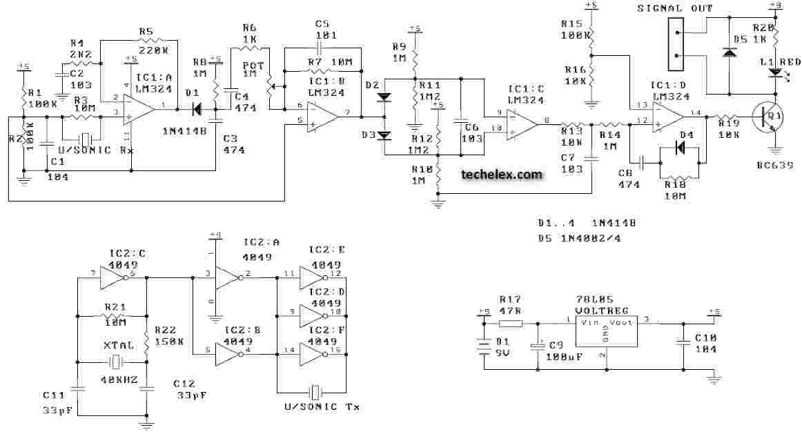
The ultrasonic transmitter emits a continuous or pulsed ultrasonic signal. When this signal encounters an object, it reflects back towards the receiver. The receiver is tuned to the same frequency as the transmitter and detects the returning signal. The time taken for the signal to return is measured, allowing the circuit to determine the distance to the object.
In the context of a remote control switch, the circuit is designed to activate or deactivate a load (such as a light or motor) based on the detection of an object within a predetermined range. If an object is detected, the circuit can trigger a relay or a solid-state switch to control the power to the load. This mechanism allows for contactless operation, enhancing convenience and safety.
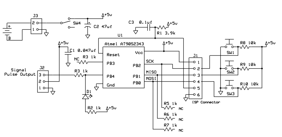
The circuit may also include additional features such as adjustable sensitivity, allowing the user to set the distance at which the switch activates. This can be achieved using variable resistors or potentiometers integrated into the circuit design. Furthermore, the circuit can be powered by a low-voltage DC source, making it suitable for battery-operated applications.
Overall, the ultrasonic switch represents an innovative approach to remote control technology, providing a reliable and efficient solution for various applications in automation and control systems.Ultrasonic Switch. C ircuit of a new type of remote control switch is described here. This circuit functions with inaudible. 🔗 External reference
Related Circuits
A PING Ultrasonic Range Finder is designed to create a system capable of detecting and measuring the distance (in millimeters) to the nearest object in front of the sensor. It functions similarly to a digital measuring tape; the user...
This ultrasonic movement detector circuit utilizes a crystal-locked circuit to achieve maximum performance from the ultrasonic transmitter. The detection circuit is designed to be more sensitive. It is advisable to verify all components against the parts list. Generally, it...
This project demonstrates a visual representation of audio volume levels through the use of LEDs that illuminate in response to music. The circuit connects to the speaker output of an audio amplifier, allowing it to gauge the audio signal's...
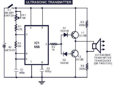
The circuit generates and transmits ultrasonic sound at frequencies between 40 and 50 kHz. It consists of a mini transmitter and a receiver circuit, where the transmitter produces ultrasonic sound, and the receiver detects this sound to activate a...
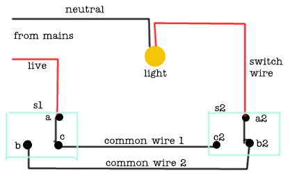
The following circuit illustrates a 2-way switch wiring electrical circuit diagram. Features include the ability to turn on the lights using switch S1, which has three terminals. The 2-way switch circuit is commonly used in residential and commercial applications to...
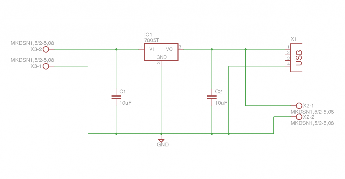
This document outlines the details of several circuits designed and built for a robot. The first circuit is a voltage regulator intended to supply power to a Raspberry Pi from a 7.2V battery. While the circuit is relatively simple,...