
Laser Power Supply Circuit

The described power supply system is designed to provide an initial high voltage for ignition applications, typically utilized in igniting gas burners or similar devices. Upon successful ignition, the output voltage stabilizes within the range of 1300 to 1500 volts, which is sufficient for maintaining the ignition process.
For scenarios requiring a higher ignition voltage exceeding the standard output of 6000 volts, the design allows for the addition of extra multiplier stages. These stages can be integrated into the circuit at points D5 and D8, which are likely configured as voltage doubler or tripler circuits, enhancing the overall voltage output through capacitive and inductive coupling techniques.
The operation of this power supply begins with a primary voltage input, which is transformed by a step-up transformer or a similar circuit element. The initial high voltage is generated through a combination of switching elements and capacitive storage, allowing for rapid discharge and ignition.
The inclusion of multiplier stages at designated points in the circuit (D5 and D8) enables flexibility in voltage output, accommodating various ignition requirements. Each multiplier stage effectively increases the voltage by a factor determined by its configuration, thereby allowing the system to achieve the necessary ignition voltage without compromising safety or operational integrity.
In summary, this power supply system is a versatile solution for high-voltage ignition applications, featuring a robust design that can be easily modified to meet specific voltage requirements through the addition of multiplier stages. The careful consideration of component selection and circuit topology ensures reliable performance and adaptability in diverse operational environments. This supply generates an initial high voltage for ignition purposes. After ignition, the supply generates about 1300 to 1500 V. If a higher ignition voltage (than the 6000 V supplied) is necessary, more multiplier stages can be added to D5 and D8.
Related Circuits

This is a design schematic for sensing the electromagnetic field. The circuit is built using a 741 operational amplifier (op-amp) IC. It can detect electromagnetic fields, including those from hidden wiring. A 1mH inductor is employed for sensing the...
A straightforward method to create a speaker transformer involves winding turns around a ferrite rod. The primary winding consists of 300 turns of 0.01mm wire, which is very fine, wound over the secondary and concluding with a loop of...
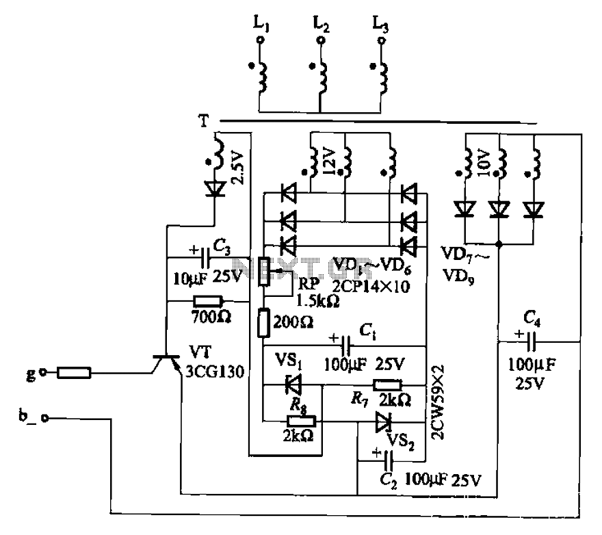
The CJ-12 Excitation Regulator is designed for automatic excitation control of small generators with a capacity of 250 kW or less. Its circuit is illustrated in Figure 7-45. The adjustment potentiometer RP allows for the modification of the measuring...
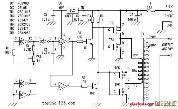
The inverter described in this text utilizes a MOS field-effect transistor and a standard power transformer. Its output power is determined by the capabilities of both the MOS field-effect transistor and the transformer, eliminating the need for complex voltage...
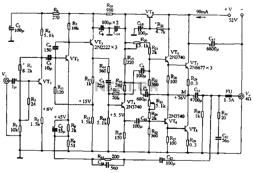
The circuit depicted in the figure is a highly technical OTL (Output Transformer-Less) amplifier circuit. It features a frequency response range of 10 Hz to 100 kHz and exhibits a total harmonic distortion of less than 0.1%, which is...
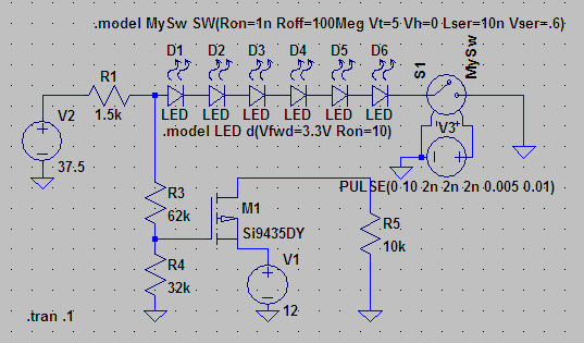
A suitable method to sense when some LEDs in a garage door opener are illuminated. A power source, potentially the same as Vout, connects to a 1.5 kΩ resistor, which then connects to six LEDs followed by a transistor....