
Latching burglar alarm II

The described circuit utilizes a Silicon Controlled Rectifier (SCR) as a key component for alarm activation. When the protective circuit, represented by resistors R1 and R2, is closed, it allows a positive voltage to be applied to the gate terminal of SCR1. This action triggers the SCR, allowing current to flow through its anode to cathode, thereby energizing the alarm system.
Resistors R1 and R2 are crucial in setting the appropriate gate voltage for SCR1. The values of these resistors can be selected based on the required gate current to ensure reliable triggering of the SCR. The alarm system, which could be a piezo buzzer or an LED indicator, is connected in series with the SCR, ensuring that the alarm is activated only when the SCR is conducting.
The circuit also includes a switch, labeled SI, which serves as the control mechanism for deactivating the alarm. When SI is opened, it interrupts the current flow to the gate of SCR1, allowing the SCR to turn off only when the current through it drops below its holding current. This design ensures that the alarm remains active until SI is manually disengaged, providing a reliable means of alerting users to potential hazards or security breaches.
In summary, the described circuit effectively utilizes an SCR to control an alarm system, with a protective circuit that ensures the SCR is triggered correctly, and a manual switch that allows for deactivation. Proper selection of component values and circuit configuration is essential for optimal performance and reliability.Closing the protective circuit (R1 to R2) applies positive voltage to the gate of SCR1 and sounds the alarm It can only be turned off with SI.
Related Circuits
The Touch Alarm circuit is commonly utilized for security purposes and is typically installed on doors. Its advantages include low cost and difficulty in detection by burglars or intruders. An example of a touch alarm circuit is designed by...
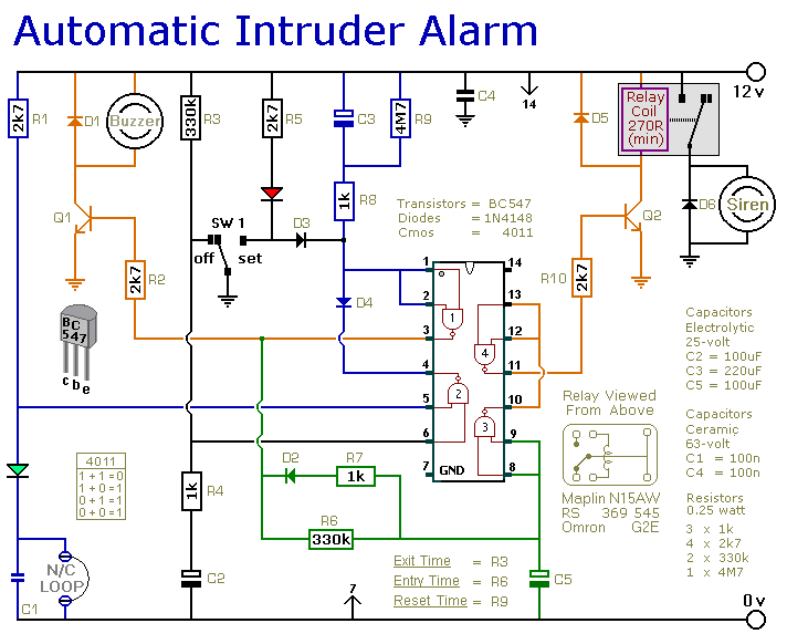
This is a simple single-zone burglar alarm circuit. Its features include automatic exit and entry delays and a timed bell/siren cut-off. It is designed to be used with the usual types of normally-closed input devices such as magnetic reed...
The Motion Sensor Switch circuit is an automatic water sprinkler controlled by a motion sensor, with the option to incorporate an alarm or light function. Before starting the construction, it is advisable to contact a local electronics component vendor...
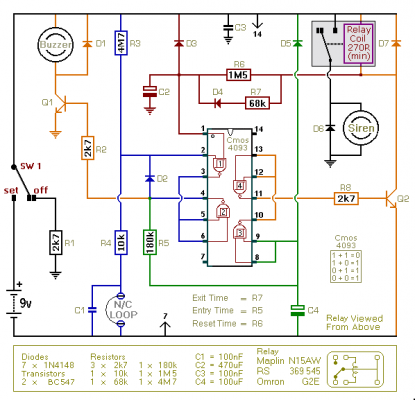
This is an improved version of the basic Garage/Shed Alarm. The Entry and Exit delays have been extended to approximately 30 seconds, and a timed siren cut-off along with an automatic reset feature has been incorporated. Additionally, the LED...
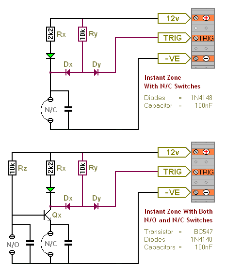
The Transistor Burglar Alarm System allows for the addition of multiple extra zones. The primary circuit is compatible with standard normally-closed input devices, including magnetic reed contacts, micro switches, foil tape, and passive infrared sensors (PIRs). An auxiliary circuit...
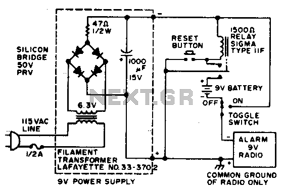
In the event of a power failure, the radio alarm activates without producing a loud siren, bell, or whistle. The alarm remains active even after power is restored and will continue until the RESET button is pressed. The described circuit...