
A Simpler Cmos Single Zone Alarm circuit
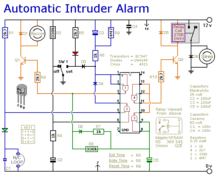
This single-zone burglar alarm circuit is designed for effective security in residential or small commercial settings. The circuit employs a simple yet effective mechanism for detecting unauthorized entry through various input devices. The normally-closed input devices create a loop that, when interrupted, triggers the alarm system. The use of magnetic reed contacts, micro switches, foil tape, and passive infrared sensors (PIRs) allows for versatile implementation depending on the specific security needs of the environment.
The operational sequence begins with the user confirming the building's security, indicated by the illumination of the green LED. By moving the switch (SW1) to the "set" position, the system enters an armed state, signified by the red LED lighting up. The 30-second exit delay allows the user to safely exit the premises without triggering the alarm. Upon re-entry, opening a door interrupts the circuit, activating the buzzer as an alert.
The relay mechanism is central to the alarm's functionality, energizing to trigger the siren if the user fails to disarm the system within the allotted time. The siren's activation is contingent on the restoration of the normally-closed loop; it will continue to sound until the loop is closed again or until the 15-minute cut-off timer is activated through the aforementioned modification.
Adjustability is a key feature of this circuit. By modifying the resistors R3, R6, and R9, the user can customize the exit delay, entry delay, and bell cut-off times according to specific requirements or preferences. This flexibility allows for a tailored response to potential security breaches while accommodating the unique characteristics of the installed components. Overall, this circuit represents an efficient and user-friendly solution for basic security needs.This is a simple single-zone burglar alarm circuit. Its features include automatic Exit and Entry delays and a timed Bell/Siren Cut-Off. It`s designed to be used with the usual types of normally-closed input devices such as - magnetic reed contacts - micro switches - foil tape - and PIRs. But it can be Easily Modified to accept normally-open trigg ering devices - such as pressure mats. It`s easy to use. First check that the building is secure and that the green LED is lit. Then move SW1 to the "set" position. The red LED will light. You now have about 30 seconds to leave the building. When you return and open the door - the Buzzer will sound. You then have about 30 seconds to move SW1 to the "off" position. If you fail to do so - the relay will energize and the Siren will sound. The maximum length of time the Siren will sound - is not fixed. The 15-minute cut-off timer only starts to run when the normally-closed loop has been restored. While the loop remains open - the Siren will continue to sound. If you want your Siren to switch off after 15 minutes - all that`s required is a Simple Modification to the trigger circuit. Then the cut-off timer will start to run the moment the alarm is activated. And the Siren will stop after 15-minutes - regardless of the state of the loop. Because of manufacturing tolerances - the precise length of any delay depends on the characteristics of the actual components you`ve used in your circuit.
But by altering the values of R3, R6 & R9 you can adjust the Exit, Entry and Bell Cut-Off times to suit your requirements. Increasing the values increases the time - and vice-versa. 🔗 External reference
Related Circuits

This simple and cost-effective ding-dong electronic doorbell circuit is based on IC 8021-2. The IC has an integrated circuitry that generates a ding-dong sound each time its pin 3 is pulled low. The sound is stored in the IC...

PARTS LIST C1 0.22 µF (224) C2 22nF (223) C3 10nF (103) C4 27pF C5 22pF C6 3.3nF (332) C7 180pF (181) C8 330pF (331) C9 3.3nF (332) C10 150pF (151) C11 82pF C12 68pF C13 220pF (221) C14...
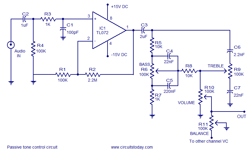
Tone control circuit utilizing an operational amplifier and a Baxandall passive tone control configuration. The overall gain is 25 dB, with a boost and cut capability of 20 dB. The circuit is powered by a dual 15V supply. The tone...
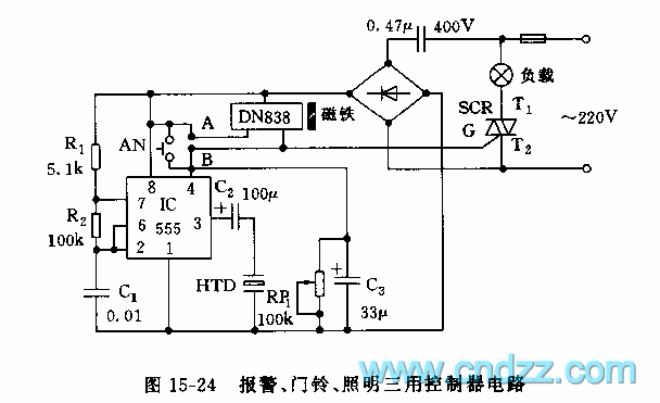
The controller circuit illustrated in Figure 15-24 consists of a switch-type Hall integrated circuit DN838 and an astable multivibrator, which is based on the 555 timer IC. This circuit is suitable for various applications, including automatic door opening, delay...
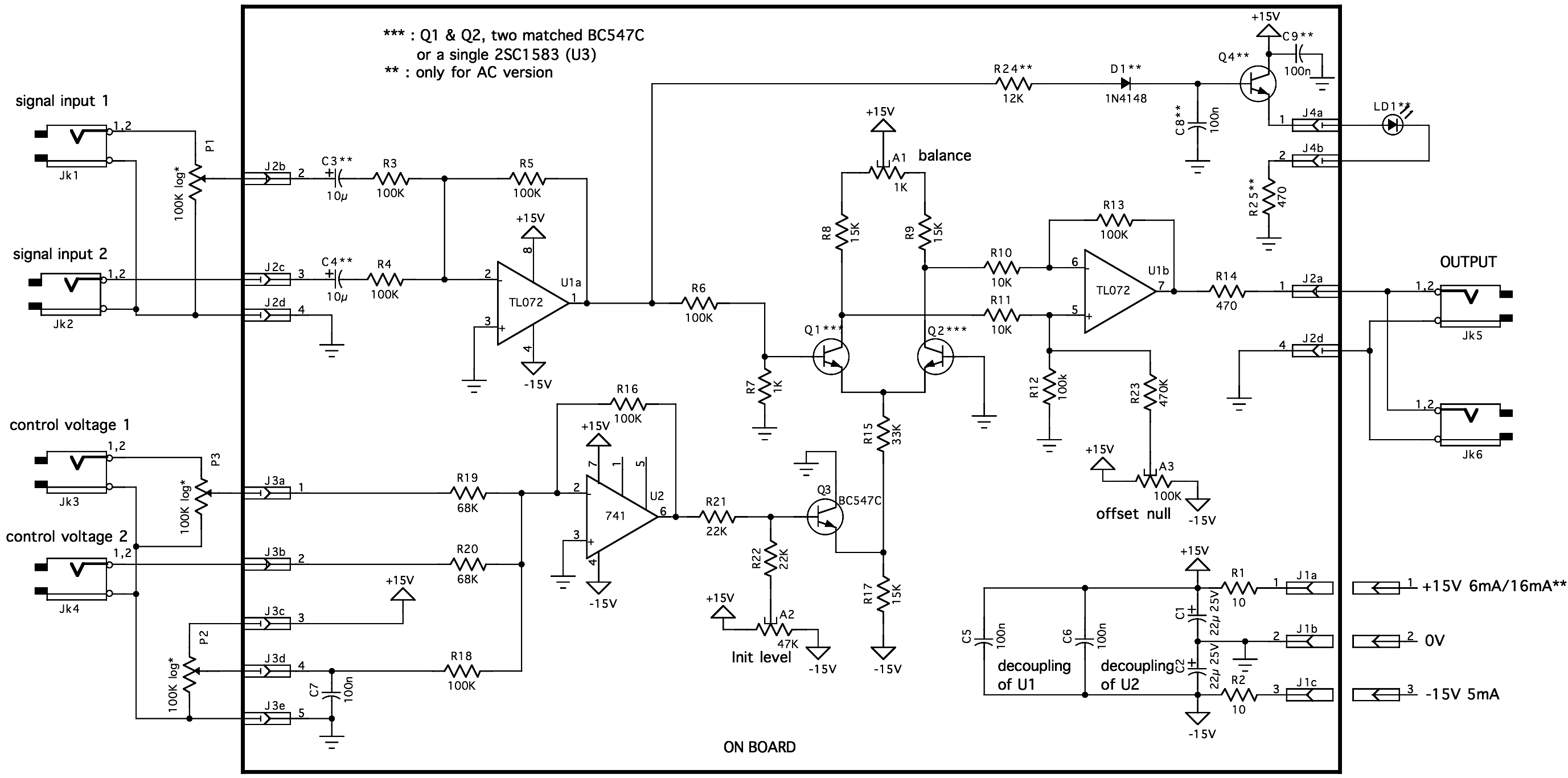
Trimming is straightforward when matched NPN transistors are utilized for Q1 and Q2, along with 1% tolerance resistors for R6 to R11. A dual trace oscilloscope, digital voltmeter (DVM), and sine wave generator are required for this process. Although...
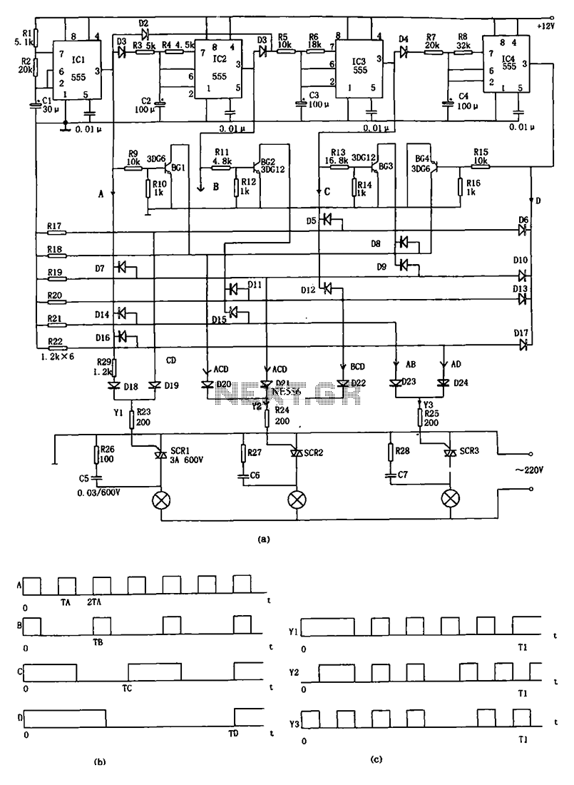
The decorative lamp control circuit is illustrated in the figure. The controller comprises a pulse generator, a frequency divider, a matrix circuit, and a thyristor control circuit. Components IC1, R1, R2, C1, and others form a multivibrator where the...