
LCD thermometer
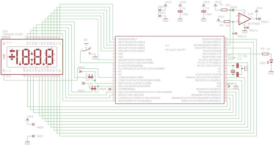
The PIC16LF1937 microcontroller serves as the central processing unit in this circuit, facilitating the control of the LCD display and the processing of temperature data from the sensor. The microcontroller features an integrated LCD driver, which simplifies the connection and control of the Varitronix VI-302 display. The display is designed to show temperature readings in degrees Celsius, providing a clear and immediate visual output.
The circuit design includes a straightforward schematic layout, where the common line connects to the ground and the segment lines are connected to the respective output pins of the microcontroller. The digital temperature sensor communicates with the PIC16LF1937 via the I2C bus, utilizing the clock and data lines for data transmission. This configuration allows for efficient data handling and minimizes the complexity of the circuit.
Power management is a critical aspect of this design. The use of the Sleep() function reduces power consumption when the device is inactive, and the microcontroller can be programmed to wake up upon a timer1 overflow event, ensuring that the temperature readings remain up-to-date without unnecessary power usage.
To program the microcontroller, the MPLAB IDE provides an integrated development environment that streamlines the coding, compiling, and debugging processes. The PICkit3 programmer facilitates the transfer of the compiled machine code from the PC to the microcontroller, enabling the device to execute the programmed instructions effectively.
Overall, this circuit exemplifies a practical application of microcontroller technology, integrating temperature sensing and display functionality within a compact and efficient design. The combination of the PIC16LF1937, the Varitronix VI-302 LCD display, and the digital temperature sensor creates a user-friendly device that operates with minimal intervention, showcasing the capabilities of modern embedded systems.This circuit is based around the PIC16LF1937 microcontroller. This chip is actually a small computer contained in a single chip, including RAM memory, EEPROM, I/O ports, CPU and so on. When you buy this chip, it comes empty with no program on it. You have to compile the source code and download the resulting machine code into it, using a PC and a
small programmer attached to the PC and the chip. To get yourself familiar with this stuff, I suggest you first read this link: Getting started with microcontrollers. The LCD display used in this design is the Varitronix VI-302 (Digikey ordernbr: 153-1022-ND), which is a static (non-multiplexed) 3.
5 digits 7-segment transflective display. It is driven by the PIC16LF1937 microcontroller which has a built-in LCD driver. Usage is very simple. There are no buttons (the switch in the schematics is currently not used). Just insert the batteries and the LCD shows the temperature in degrees Celsius. The diagram is really simple. One common line and a lot of segment lines are connected to the LCD display. The digital temperature sensor is connected to the clock and data lines of the PIC`s I2C bus. The software is written in C ( Hi-tech C supporting Microchip ). It uses power saving techniques such as Sleep() and wake up from sleep after timer1 overflow. For programming you need the Microchip MPLAB IDE and a PICkit3 compatible programmer. You also need the Hi-tech C compiler (the lite version, free to download, will do). Zip file containing all source code, header files and project files: Link to MPLAB project. The project file to open is called LCD_demo. mcp, the workspace file is LCD_demo. mcw. 🔗 External reference
Related Circuits
This straightforward high-level design illustrates the structure of the product. The integrated circuit reacts to button presses and detects temperature through a probe, displaying the temperature on an LCD and activating a buzzer upon completion. A more detailed diagram...
The LM135/235/335 temperature sensor is designed for ease of absolute temperature reading, providing all positive values for any frequency. This is why a voltage of 2.7315V is observed at 0 degrees. The LM135/235/335 series of temperature sensors are precision devices...

An inexpensive electronic thermometer is capable of measuring temperatures over a range from -30°F to +120°F. A diode-connected 2N3904 transistor used as the temperature sensor forms a voltage divider with R1. As temperature increases, the voltage drop across the...
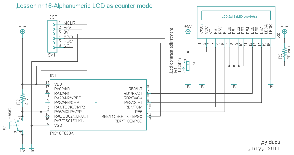
The communication technique with the LCD is similar to the previous lesson. In this experiment, a counter that counts from 0000 to 9999 has been added. The counter increments with a 1-second delay. The communication with the LCD will...
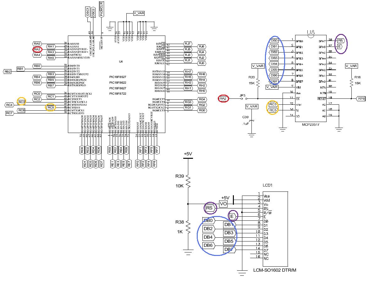
Learn to use the LCD display on the PIC 18 Explorer board with the SPI library. The SPI library will be utilized to easily display characters on the LCD. Additionally, the operation of I/O expanders will be explored. The PIC...
This circuit is designed for precise centigrade temperature measurement. It includes a transmitter section that converts the sensor's output voltage, which is proportional to the measured temperature, into frequency. The output frequency bursts are transmitted through the mains supply...