
Lead-Acid Battery Charger
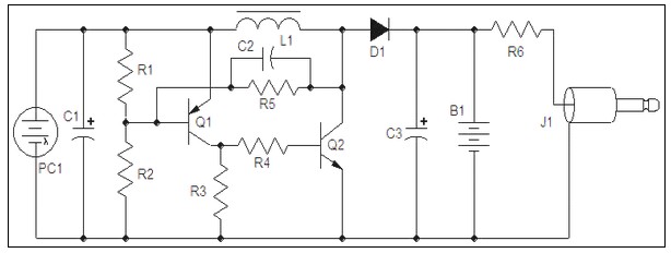
The described circuit functions as a half-wave rectifier designed to charge a battery during each positive half-cycle of the input AC voltage. The rectification is achieved through a silicon-controlled rectifier (SCR), which is triggered to conduct during each half-cycle, allowing current to flow into the battery. The two 1.8 ohm resistors in parallel create a voltage drop that is utilized to charge a 47 µF electrolytic capacitor. This capacitor, once charged, activates a BC547 transistor, which subsequently reduces the gate voltage to the SCR, turning it off.
As the battery voltage rises, the operation of the circuit is monitored by a dedicated voltage monitoring block. This block consists of a transistor and a zener diode, along with several resistors (8.2 kΩ, 1 kΩ, 1.5 kΩ, and 150 Ω) and a potentiometer. The voltage across the battery is continuously assessed, and when it reaches a threshold of approximately 13.75 volts, the voltage drops across the resistors trigger the voltage monitor transistor. This action effectively disables the turn-on transistor, leading to a cessation of current flow from the SCR to the battery.
The SCR operates in two states: on and off. During the conduction phase, it delivers a high pulse of current limited by the plug pack's capacity. The SCR is rated for 0.8 amps but can withstand surges of up to 10 amps for brief periods. The current delivery is controlled by the average charging current, which is designed to be between 300 mA and 400 mA, primarily determined by the two 1.8-ohm resistors.
When the battery reaches a fully charged state, the circuit utilizes an LED indicator that begins to flash. This flashing is facilitated by the interaction of the 2.2 kΩ resistor and the 47 µF capacitor within the voltage monitor section. The charging process for the capacitor occurs through a diode linked to a BC557 transistor, which, along with the 150 Ω resistor, directs current to the battery's negative terminal. Once the battery is fully charged, the voltage monitor activates, shutting off the turn-on section and thus preventing overcharging. This is achieved by bringing down the potential of the capacitor and allowing the 150 Ω resistor to drop below the negative rail, effectively holding the circuit in an off state until the battery voltage drops again.The circuit is actually a half-wave rectifier. It only charges the battery on every half cycle. The plug pack doesn't like this as it leaves residual flux in the core of the transformer and causes it to overheat. But that's the only drawback with the circuit. The SCR turns on during each half cycle and current flows into the battery. A voltage is developed across the two 1R8 resistors (in parallel) and this voltage is fed into the 47u electrolytic.
It charges and turns on the BC547 transistor. The transistor robs the SCR of gate voltage and the SCR turns off. The energy in the 47u feeds into the transistor but after a short time it cannot keep the transistor turned on. The transistor turns off and the SCR switches on and delivers another pulse of current to the battery. As the battery charges, its voltage increases and this is monitored by the "Voltage Monitor" block. The circuit is very complex and one way to look at the operation is to consider the top rail as a fixed rail and as the battery voltage increases, the rail connected to the negative terminal of the battery is pushed down.
This lets you see how the "Turn On" transistor is activated and how the "Voltage Monitor" components create voltage drops across each of them. The "Voltage Monitor" components consist of a transistor and zener diode as well as an 8k2 resistor, the 1k pot, a 1k5 resistor, a 150R resistor and a signal diode.
The signal diode is actually part of the flasher circuit and we discuss its operation later. As the voltage across the battery increases to 13.75 volts, each resistor in the "voltage detecting network" will have a voltage drop across it that corresponds to the resistance of the resistor. The diode will have a constant 0.7v across it. The voltage on the wiper of the pot will be about 3.25v and the voltage across the zener will be 10v.
This leaves 0.6v between the base and emitter of the Voltage Monitor transistor. This voltage is sufficient to turn the transistor ON. When the Voltage Monitor transistor turns ON, it robs the "Turn On" transistor of base-emitter voltage and the circuit turns off. The SCR has only two states: ON and OFF. During the half-cycle when it is turned on, the battery gets a high pulse of current and the current is only limited by the capability of the plug pack.
There are no electrolytics to allow very high pulses of current to be delivered and this is fortunate as the SCR is only a 0.8 amp device, but will endure surges of 10amp for half a cycle. Whenever the SCR is triggered into conduction during the half cycle of its operation, it remains in conduction until the voltage delivered by the plug pack falls to zero.
This is when the SCR turns off. When the plug pack delivers a negative voltage to the top rail and a positive voltage to the lowest rail, the SCR is not triggered into conduction and none of the components in the circuit deliver current to the battery. The SCR delivers current for a few half-cycles and then it is turned off for a few cycles. This is how the average current delivered to the battery is controlled. The circuit is designed to deliver about 300 - 400 mA average charge-current. The actual value is determined by the 1R8 resistors. When the battery is fully charged, the indicator LED begins to flash. The flashing is produced by the 2k2 resistor and 47u (connected to the voltage monitor section). When the battery is charging, the 47u is charged via the diode connected to the BC557 transistor and through the 150R and signal diode to the negative of the battery.
When the battery is fully charged, the Voltage Monitor section turns ON and turns off the "Turn ON" section. This removes the voltage on the positive side of the 47u and the positive side is brought to the negative rail via the 2k2 resistor.
This brings down the negative side of the 47u and the 150R resistor is allowed to drop below the negative rail due to the presence of the diode, as the diode becomes reverse-biased. This holds the circuit in the "off" condition, as the voltage monitor section sees an extra voltage across it and thinks the battery it is "over-charged."
🔗 External reference
Related Circuits
This circuit utilizes the widely available LM3914 integrated circuit (IC). The LM3914 is straightforward to operate, does not require external voltage regulators due to its built-in voltage regulation, and can be powered from nearly any voltage source. This makes...
A mobile phone charger powered by a solar cell power supply is described. This system utilizes a dual comparator circuit that connects the solar panel to the battery when the voltage at the battery terminal is low and disconnects...
Charging current is about 100+mA, which is the internally-limited maximum current of the LP2951. For those wondering, this is compatible with just about any single-cell li-ion battery since li-ion can generally accept a charging current of up to about...
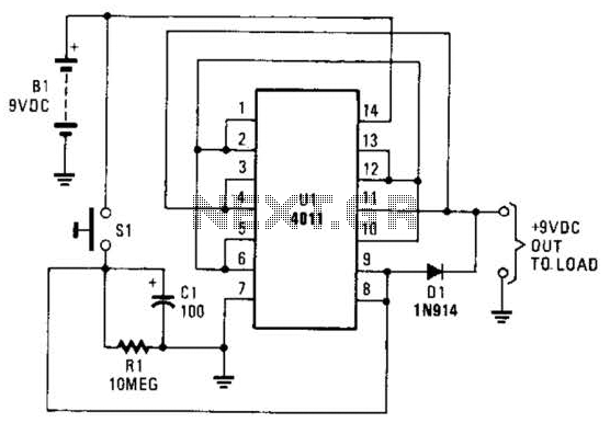
This battery saver circuit can automatically turn off a small piece of test equipment after a desired period of time, allowing for worry-free operation in a workshop environment. The circuit utilizes a CD4011 integrated circuit (IC) to function as...
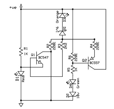
This circuit is a 12V battery checker that utilizes three LEDs to indicate different voltage levels. The red LED illuminates when the battery voltage is between 8V and 10V, the orange LED activates at voltages ranging from 10.5V to...
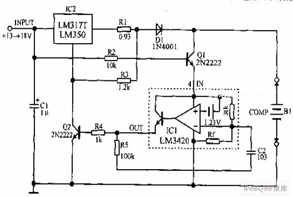
A lithium-ion battery charging circuit is illustrated above. Initially, when charging begins, if the battery voltage is below 8.4V, the output of IC1 is inactive. As a result, Q2 remains off, and the LM317 operates in constant current mode....