
mobile phone charger powered solar cell
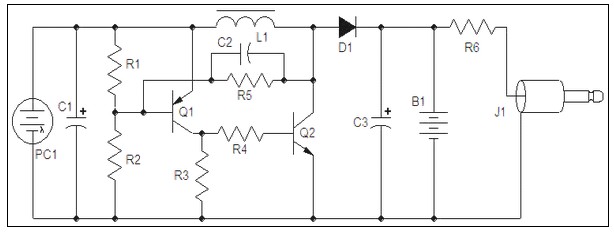
The solar-powered mobile phone charger operates by harnessing solar energy through a photovoltaic panel, which converts sunlight into electrical energy. The dual comparator circuit serves as the core control mechanism, ensuring that the battery is only charged when necessary. The first comparator monitors the battery voltage; it engages the connection to the solar panel when the voltage drops below a predefined threshold, allowing the battery to receive charge. Conversely, when the battery voltage exceeds the upper threshold, the comparator disconnects the solar panel to prevent overcharging, which can damage the battery.
The use of resistor R3 is critical as it scales the battery voltage to a suitable level for the comparators, ensuring accurate voltage readings. The IC2, which houses the dual comparators, is responsible for managing the charging process, providing a reliable means to maintain the health of lead-acid batteries throughout their charging cycles.
For lithium batteries, the dedicated charger circuit incorporates the LM317T voltage regulator to maintain a steady output voltage while charging. The ICL7665 microprocessor supervisory circuit monitors the voltage levels, providing alerts for both overvoltage and undervoltage conditions to protect the battery from potential damage. The design stipulates a constant charging current of 60 mA, which is optimal for AA lithium cells. The charging process is carefully monitored, and once the battery voltage reaches the cutoff point of 2.4 V per cell, the charging is terminated to prevent overcharging, which can lead to safety hazards or battery degradation.
Overall, this solar-powered charger design effectively integrates both lead-acid and lithium battery charging capabilities, making it a versatile solution for mobile phone charging applications in off-grid scenarios. Proper implementation of these components ensures efficient energy conversion and battery management, enhancing the longevity and performance of the batteries used.Mobile Phone Charger Powered using Solar Cell power supply. Go to that page to read the explanation about above power supply related circuit diagram. The solarbattery chargercircuit isnothing but adualcomparatorthat connects thesolar panelto the batterywhen thevoltage atthelatter terminalis lowand disconne cted ifexceeding a certain threshold. Since itisonlybymeasuring thebattery voltage, it is especially intendedfor lead batteries, aelectrolyteliquid or gelled, thatadaptthebestofthisway. The battery voltageseparatedbyR3before being fedtothe two comparatorsinIC2, . This Lithium batterychargercircuitis dedicatedto chargelithiumbatteries. Ituses 2chips, voltage regulatorLM317TandICL7665warnsmicroprocessors( Ps)ofovervoltageand undervoltageconditions.
Charging is completed with a constant current of 60 ma for Aa cells to a cutoff voltage of 2. 4 V per cell, at which point the charge should be terminated. The. 🔗 External reference
Related Circuits
Charger for car battery power supply. Refer to the webpage for an explanation of the power supply-related circuit diagram. The battery charger indicator circuit described above enhances the appearance of a simple battery charger. This circuit serves as a...
A monolithic 555-type timer serves as the core component of this straightforward automobile voltage regulator. When the timer is inactive, resulting in a low output at pin 3, the power Darlington transistor pair remains off. If the battery voltage...
This document serves as a supplementary guide to numerous existing resources that detail the construction of a USB charger. It is assumed that the reader possesses a basic understanding of electronics. The construction of a USB charger typically involves a...
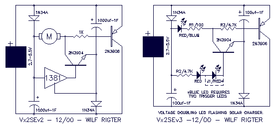
The Vx2SE is a simple discrete voltage-doubling SE for driving an LED. If the load is a red or green LED, J1 is used together with just one red or green LED for threshold detection (no 1381). For driving...
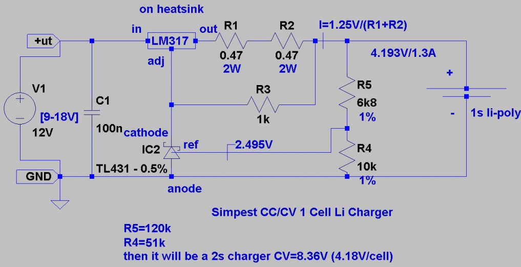
This is a Lithium-ion charger for LiPo batteries. The circuit schematic illustrates the configuration for charging a single 3.7V LiPo battery, but the voltage can be adjusted to charge multiple batteries in series. The LiPo charger establishes a current...
An output voltage sufficient to bridge a one-inch gap can be generated from a 12-V power source. A 555 timer integrated circuit (IC) is configured as an astable multivibrator, producing a narrow negative pulse at pin 3. This pulse...