
LED Boost Circuit
1. Trim the board to the final size you want before assembly. The board may be sawn, sanded, or filed to shape. It is designed to be round should you want, a bit less than the diameter of an AA cell.
The circuit described is a boost driver designed to convert low input voltages into a higher output voltage suitable for driving LED lights. The operational voltage range of 0.8 to 3 Volts allows for flexibility in power source selection, accommodating various battery types such as Lithium-based cells, NiMH, and alkaline batteries. The circuit can effectively utilize the remaining charge in batteries, making it an efficient solution for maximizing energy usage.
The LED driver operates by boosting the input voltage to a level that can adequately power the LED while providing a candle-like illumination. The design prioritizes safety and efficiency, ensuring that even at lower input voltages, the circuit can still produce light, albeit at reduced intensity. This feature is particularly beneficial for applications where battery life is critical, allowing for a gradual dimming of the LED as the battery discharges.
The construction of the printed circuit board (PCB) is straightforward, with recommendations for trimming the board to the desired size. The design can accommodate a circular form factor, which is advantageous for compact applications, especially in handheld devices like flashlights. The board can be easily modified using standard techniques such as sawing, sanding, or filing, providing users with the ability to customize the dimensions to fit specific enclosures or designs.
Overall, this boost driver circuit presents a versatile and efficient solution for LED lighting applications, particularly in scenarios where battery conservation and compact design are essential.The completed board may be driven by voltages between .8 and 3 Volts. While the basic design goal was candle like light from a single cell, the values used were chosen to allow safe operation from 3 Volts so you can, for example, use it to drain the last bit of energy out of used Lithium based cells from flashlights. This means that you can also drive it from a fresh 123 cell at full brightness (for 16 hours or so) or two NiMH, alkaline or other cells in series.
While the current consumption (and therefore light output) goes down with supply voltage, some light is produced even with very low inputs. How to assemble the Boost Driver Printed Circuit Board 1. Trim the board to the final size you want before assembly. The board may be sawn, sanded or filed to shape. It is designed to be round should you want, a bit less than the diameter of an AA cell 🔗 External reference
Related Circuits
Environmental interference can affect the transfer switching, leading to the production of burrs in confidence disgrace. The switch position signal will control the computer system with the reliability of lanthanum burrs. The work has some impact. Glitches are typically...
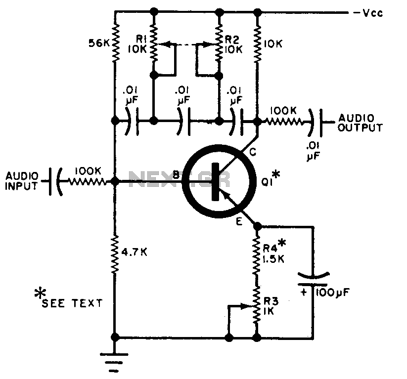
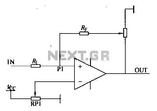
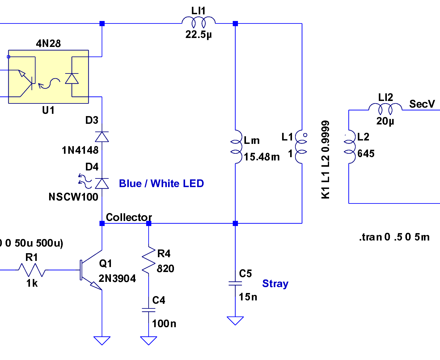
The circuit can be selectively tuned to two closely related tones. The selective frequency is determined by the values of the feedback circuit connected to the collector and base of Q1, which includes capacitors and resistors. When the specified...
The LED guard-rail tube, also known as the decorative tube, is an advanced LED illumination product designed for decorative purposes. It utilizes red, green, and blue LEDs as light sources, employing microelectronics and digital technology to create color chasing...
The yellow wires on the far right serve as temporary power connections, allowing battery power to enter through the contact studs located in the large holes that press against the radio's battery terminals. The cable in the lower right...
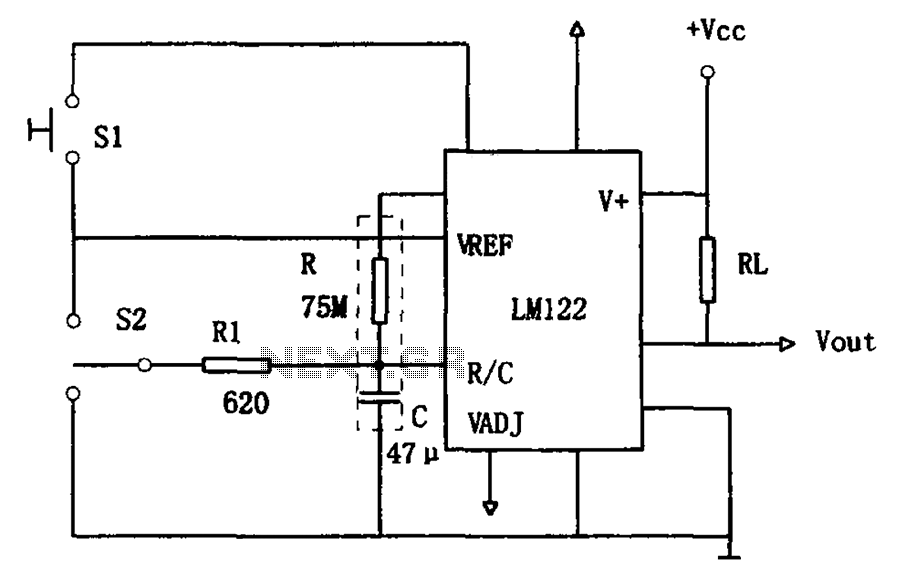
The circuit utilizes an LM122 timer, as illustrated in Figure 1, to manage various timing operations, including starting, resetting, and halting the process midway through. The operation of the circuit is governed by switching mechanisms. Switch S1 initiates the...
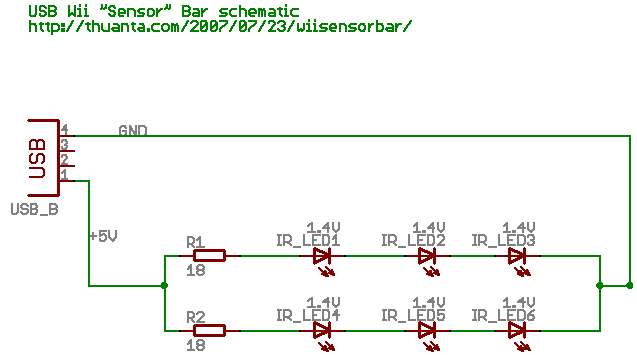
The following circuit illustrates the Wii "Sensor" Bar Project Circuit Diagram. Features include a series of infrared LEDs positioned at both ends of the bar, which emit infrared light. The Wii Sensor Bar is a crucial component for the Wii...