
gps voice interface circuitry
The circuit described involves a temporary power supply setup using yellow wires, which connect to the battery terminals of a radio via contact studs. This arrangement is essential for providing power to the radio during testing or configuration phases. The use of large holes for the contact studs allows for a secure connection that can handle the necessary current flow.
The USB cable, which is incorrectly color-coded, plays a critical role in audio communication. It connects the helmet's earbud and microphone, enabling two-way audio functionality. Proper identification and management of cable connections are vital to ensure clear audio transmission and prevent any potential signal interference.
The mention of component pads indicates a custom circuit board design where not all available spaces are populated. This choice may stem from a strategic decision to optimize performance without overcomplicating the circuit with unnecessary components. The absence of certain parallel bypass capacitors suggests a focus on minimizing self-resonance effects, which can complicate signal integrity in high-frequency applications.
The integration of the TinyTrak3+ cable into the DB9 footprint is a key aspect of this design. This footprint is typically used for serial communication and its repurposing from the ICOM IC-Z1A interface indicates a modular approach to circuit design. Such adaptability allows for the reuse of components, promoting efficiency and cost-effectiveness in electronic system development.
Future plans include the installation of the Wouxun KG-UV3D, which suggests an ongoing evolution of the system. The anticipation of rainy days for this work implies that environmental conditions may dictate the timeline for completing the modifications, highlighting the practical considerations that engineers must often navigate in the field.The yellow wires on the far right are temporary power connections; battery power enters through the contact studs in those large holes that press against the radio`s battery terminals. The cable in the lower right is the mis-color-coded USB cable that carries audio to & from the earbud & mic on the helmet.
Not all the pads have components; I didn` t use all the parallel bypass cap locations because I wasn`t up for protracted self-resonance measurements. The TinyTrak3+ cable solders into the empty DB9 footprint over on the left. I must cannibalize that from the ICOM IC-Z1A interface in Mary`s bike after the next Wouxun KG-UV3D arrives; with any luck, there`ll be a rainy day or two for that work.
🔗 External reference
Related Circuits
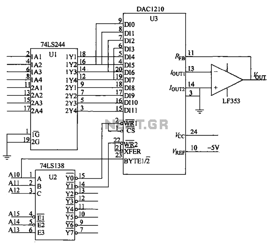
CMOS interface circuit with PMOS cross-coupled PMOS integrated circuit featuring high input impedance, where the input current can be ignored. The CMOS and PMOS interface circuit is illustrated in the accompanying figure. The CMOS interface circuit utilizing PMOS cross-coupled configurations...
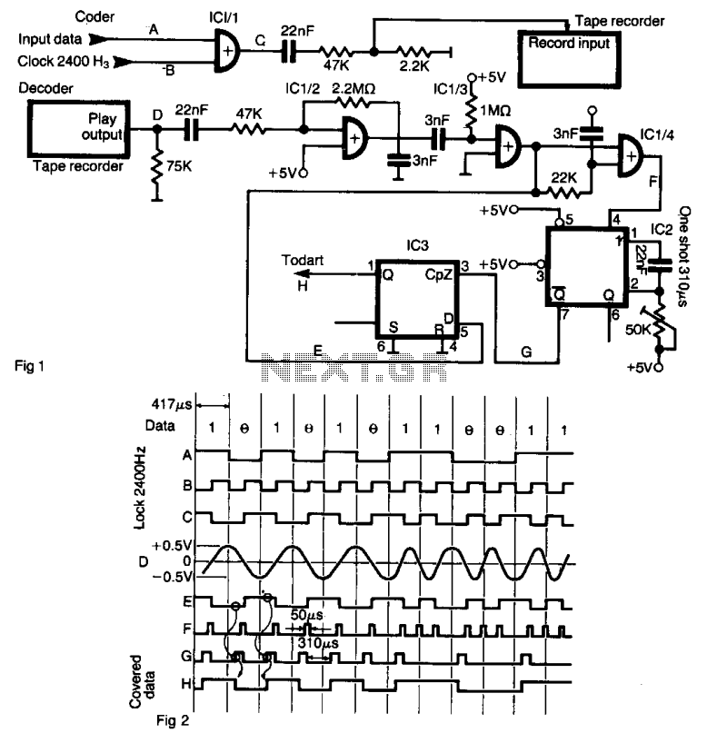
The interface enables data to be recorded on a standard tape recorder at a speed of 2400 bits per second. The serial data stream is encoded with a clock frequency of 2400 Hz using an XOR gate (IC 1/1)....
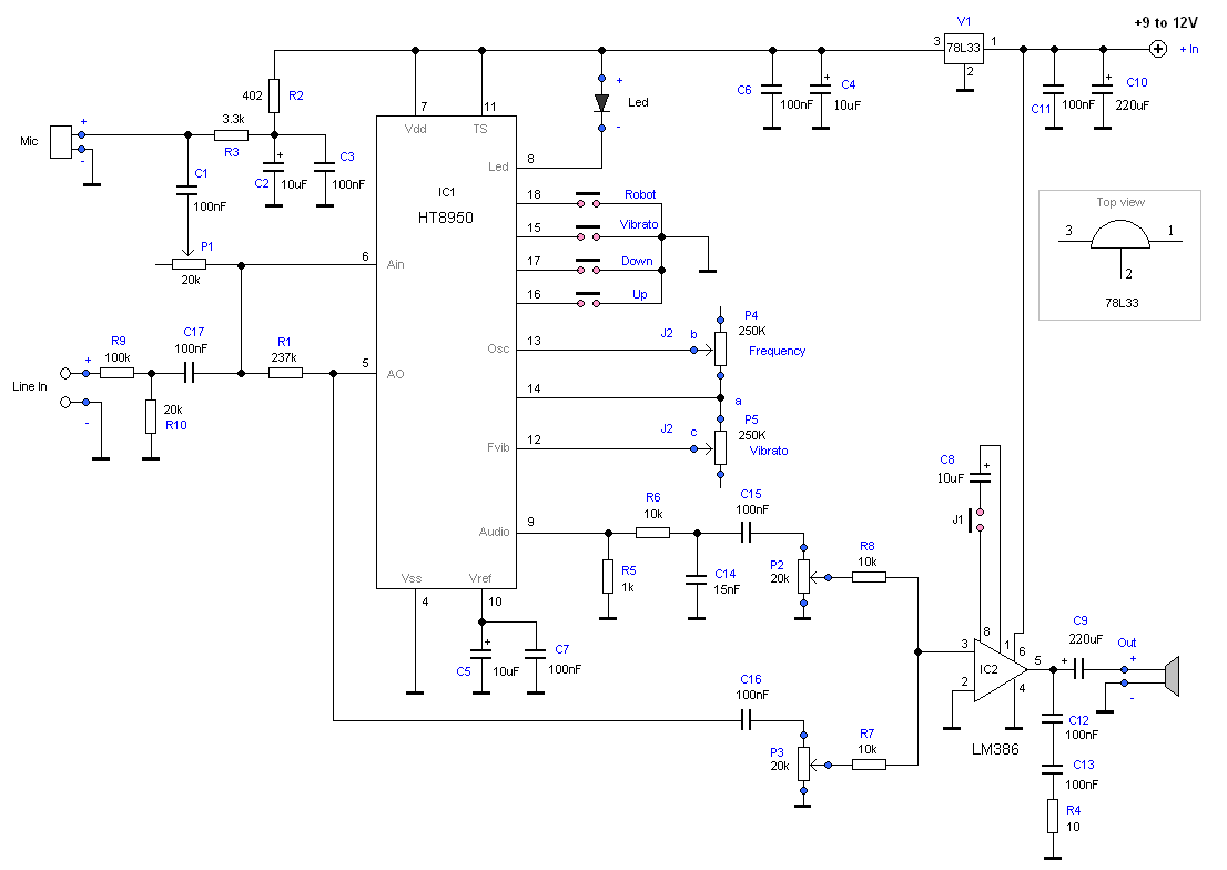
This project demonstrates the construction of a robot voice generator utilizing the HT8950 integrated circuit, which is a robust voice modulation IC. The circuit features a robot function, a vibrato function, and additional capabilities. The robot voice generator circuit employs...
This circuit is designed to produce DMX output for entertainment lighting from a PC. It offers flexibility in circuit configurations. By opting for no isolation, the setup requires only a PIC microcontroller and a standard RS-485 driver, with an...
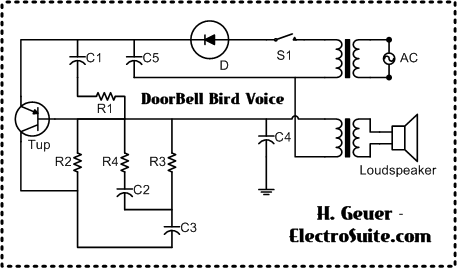
This is a Doorbell Bird Voice Electro Suite designed to replace the old doorbell, providing a refreshing and exciting experience with a new doorbell system. The Doorbell Bird Voice Electro Suite is an innovative electronic circuit designed to enhance the...
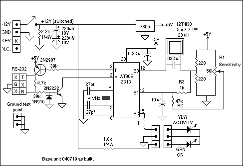
The purpose of the terminal interface is to allow my computer to communicate with Minimum Mass Wireless Coupler equipped devices using a terminal emulator program. Consequently, the Base Unit is basically an RS-232 interface and Minimum Mass Wireless Coupler....
Warning: include(partials/cookie-banner.php): Failed to open stream: Permission denied in /var/www/html/nextgr/view-circuit.php on line 713
Warning: include(): Failed opening 'partials/cookie-banner.php' for inclusion (include_path='.:/usr/share/php') in /var/www/html/nextgr/view-circuit.php on line 713