
LED Chaser
The described circuit is a simple LED chaser using a 4011 NAND gate IC, which serves as the primary component for generating the oscillation needed to drive the LEDs. The 4011 contains four NAND gates, and in this application, two of them are configured to create a basic oscillator circuit.
The oscillator operates by utilizing the feedback mechanism inherent in the NAND gate configuration. When powered, the output of one NAND gate is connected to the input of the second, creating a loop that causes the gates to toggle between high and low states. This oscillation produces a square wave signal that can be used to drive a series of ten LEDs arranged in a chaser pattern.
To implement the LED chaser effect, the output from the NAND gate oscillator is further processed using a series of flip-flops or shift registers, which can be constructed from additional NAND gates or other logic ICs. Each flip-flop would control one LED, lighting it sequentially as the signal propagates through the circuit. This provides the visual effect of lights "chasing" each other along the strip of LEDs.
Powering the circuit requires a suitable DC power supply, typically in the range of 5V to 15V, depending on the specifications of the LEDs and the NAND gates used. Current-limiting resistors should be placed in series with each LED to prevent excessive current flow, ensuring longevity and consistent brightness.
The design can be further enhanced by incorporating a potentiometer to adjust the speed of the chaser effect, allowing for customization of the blinking rate. Additionally, the circuit can be expanded to include more LEDs or different configurations, such as bi-directional chasers or varying patterns, by modifying the control logic.
Overall, this simple LED chaser circuit demonstrates the versatility of the 4011 NAND gate and provides an engaging visual display suitable for various applications, from decorative lighting to educational demonstrations in electronics.I don`t know why, but people like blinking lights. You see LED chasers everywhere, in TV shows (Knight Rider), movies, and store windows. This schematic is my version of a simple 10 LED chaser. There is no 555 timer used because at my local electronics store they are over $4 Cdn. Instead, an oscillator made up of two sections of a 4011 NAND gate is employed. This chip is very inexpensive and extremely common. 🔗 External reference
Related Circuits
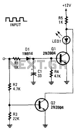
This circuit can be utilized to detect a stuck output or node in a circuit, or a loss of data or pulses. The pulse train charges capacitor C1 and biases transistor Q1 on, which illuminates the LED. If the...
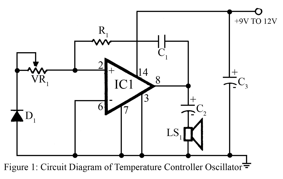
The output frequency or tone of this oscillator circuit varies with the temperature at which the input germanium diode is maintained. The reverse resistance of D1 ranges from 500 ohms to 10 k ohms when the temperature fluctuates between...
7-Segment Common LED UV Exposure Box Circuit Diagram. Features: Utilizes Stan Ocker's circuit design, employing a PIC16F84 microcontroller to count and display the time. The 7-Segment Common LED UV Exposure Box Circuit is designed for applications requiring precise timing and...
Almost any 2x16 character LCD module with Hitachi HD44780 controller chip will work. The LCD pin numbers on the schematic are not valid for all LCD modules. Please check the actual signal names on your particular LCD module. The...
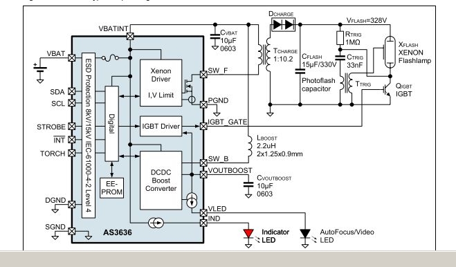
The AS3636 is a highly integrated photoflash charger that includes an IGBT driver, an inductive DC-DC boost autofocus/video LED driver, an indicator LED driver, and incorporates system-level ESD protection. The AS3636 is designed for efficient photoflash charging applications, providing a...

The circuit can be divided into four sections: power supply, touch sensor, microcontroller, and LED driver. The touch sensor is connected to the frame. The circuit architecture consists of four primary sections, each serving a distinct function to ensure the...