
7Segment Common LED UV Exposure Box
The 7-Segment Common LED UV Exposure Box Circuit is designed for applications requiring precise timing and display functionalities, particularly in UV exposure processes. The core of the circuit is the PIC16F84 microcontroller, which is programmed to manage the timing operations and control the display of the 7-segment LEDs.
The circuit typically consists of the following components: a PIC16F84 microcontroller, a set of 7-segment displays, resistors, capacitors, and a power supply. The microcontroller is responsible for counting the elapsed time during the exposure process. It can be programmed to start counting when the UV light is activated and to stop once the desired exposure time is reached.
The 7-segment displays are connected to the microcontroller through a series of output pins. Each segment of the display is driven by a specific pin on the PIC16F84, allowing for the representation of numerical values from 0 to 9. Additional logic may be integrated to handle transitions between tens and units, ensuring that the display accurately reflects the total elapsed time.
Resistors are used to limit the current flowing through the LEDs of the 7-segment displays, preventing damage and ensuring longevity. Capacitors may be included in the circuit to stabilize the power supply and filter out noise, which can be crucial for maintaining accurate timing.
In summary, the 7-Segment Common LED UV Exposure Box Circuit is a practical implementation of timing and display technology, effectively utilizing the capabilities of the PIC16F84 microcontroller to manage UV exposure processes accurately. This design can be adapted for various applications in fields such as photography, material science, and electronics, where controlled exposure to UV light is essential.Description: 7Segment Common LED UV Exposure Box Circuit Diagram. Features: used Stan Ocker`s circuit, uses a PIC16F84 to count and display the time .. 🔗 External reference
Related Circuits
A common collector amplifier circuit structure and its key components are outlined. The composition of the common collector amplifier circuit is fundamentally similar to that of a common emitter amplifier circuit, with two notable exceptions: one is the collector...
.jpg)
This article contains an assembly language listing that requires MAC/65 or the Atari Assembler Editor, along with access to an EPROM burner. The previous three installments were published in the January, February, and March 1985 issues of Antic. This...
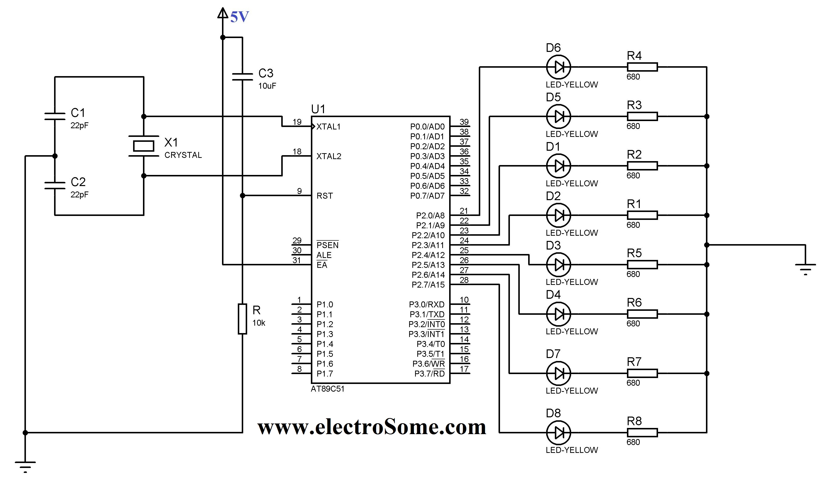
The 8051 controller is mask-programmable, meaning it is programmed during manufacturing and cannot be reprogrammed afterward. However, the AT89C51 microcontroller, a derivative of the 8051, is reprogrammable. This device includes a timer, a serial port interface, and interrupt control,...
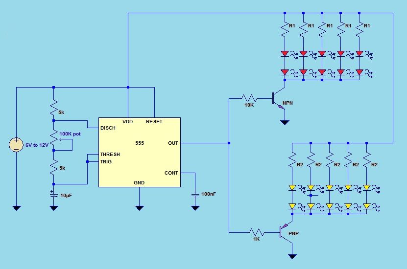
This project utilizes a 555 timer integrated circuit (IC) in an 8-pin configuration to control multiple LEDs. It is designed for quick assembly and allows for the adjustment of timing functions. The circuit employs a 555 timer in astable mode,...
This circuit is a 73 MHz halogen lamp radio-controlled system. Its purpose is to control the power state of a halogen lamp using a remote control. When the push button on the remote control is pressed, the power state...
The circuit is based on the IC1 that is 555, for the creation of alternate flashes from the two led D1-2, that can be also different colour. The frequency of alternation can be regulated from the trimmer R3 and...
Warning: include(partials/cookie-banner.php): Failed to open stream: Permission denied in /var/www/html/nextgr/view-circuit.php on line 713
Warning: include(): Failed opening 'partials/cookie-banner.php' for inclusion (include_path='.:/usr/share/php') in /var/www/html/nextgr/view-circuit.php on line 713