
Medium Wave radio reciever circuit

The radio receiver circuit is designed to utilize a variety of transistors, specifically the ZN414, MK484, and TA7642, which are commonly used in low-power AM radio applications. Each of these transistors serves as a fundamental component in the circuit, contributing to the overall functionality and performance of the receiver.
The ZN414 is a silicon integrated circuit designed for use in AM radio receivers. It features high sensitivity and low power consumption, making it suitable for battery-operated devices. The MK484 is another integrated circuit that provides similar functionality, with a focus on low voltage operation. The TA7642 is a versatile AM radio receiver IC that offers good selectivity and sensitivity, making it a popular choice for hobbyists and engineers alike.
In the schematic, the chosen transistor can be connected to an antenna, which captures radio frequency signals. The output from the antenna is fed into the transistor's input stage, where it is amplified. The amplified signal is then processed through a series of stages, including demodulation and filtering, to extract the audio signal from the radio frequency carrier wave.
The circuit typically includes passive components such as resistors, capacitors, and inductors, which are essential for tuning the receiver to specific frequencies and for stabilizing the operation of the transistor. The design may also incorporate a variable capacitor to allow for fine-tuning of the reception frequency.
Power supply considerations are critical, as these transistors function effectively at low voltages, often in the range of 1.5V to 9V. Proper decoupling capacitors should be included to minimize noise and ensure stable operation.
Overall, the flexibility to use any of the specified transistors allows for customization based on availability, desired performance characteristics, and specific application requirements, making this radio receiver circuit a versatile option for radio enthusiasts and engineers.This radio reciever can work with any of the following transistors zn414, mk484 or ta7642. 🔗 External reference
Related Circuits
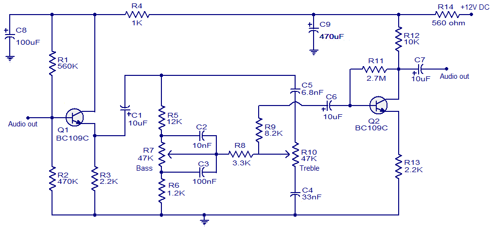
This simple tone control circuit is designed based on the renowned Baxendall tone control circuitry. The circuit can provide a maximum cut or boost of approximately 12 dB at both 10 kHz (treble) and 50 Hz (bass). Additionally, both...
The technical parameters of high-speed optocouplers include a rise time (t1) of less than or equal to 300 ns, a circuit transfer ratio (CTR) of 50%, an isolation voltage (VSO) of at least 15,000 V, and an output transistor...
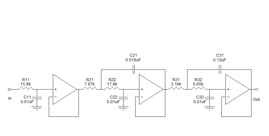
Assistance is needed to understand a schematic. Most components are clear, except for the triangular symbols which are likely operational amplifiers (op-amps). Clarification is required on their implementation and arrangement. The current diagram is intended for testing with a...
This circuit emits an intermittent beep or flashes an LED when the water level in a container reaches a predetermined height. It is designed to be mounted on top of the container, such as a plastic tank, using two...

This circuit has a long history, originating from an idea by Rich Piotter and later refined by Wilf Rigter and Bruce Robinson. The final result does not include the necessary motor drivers, which are typically H-bridge based, but presents...
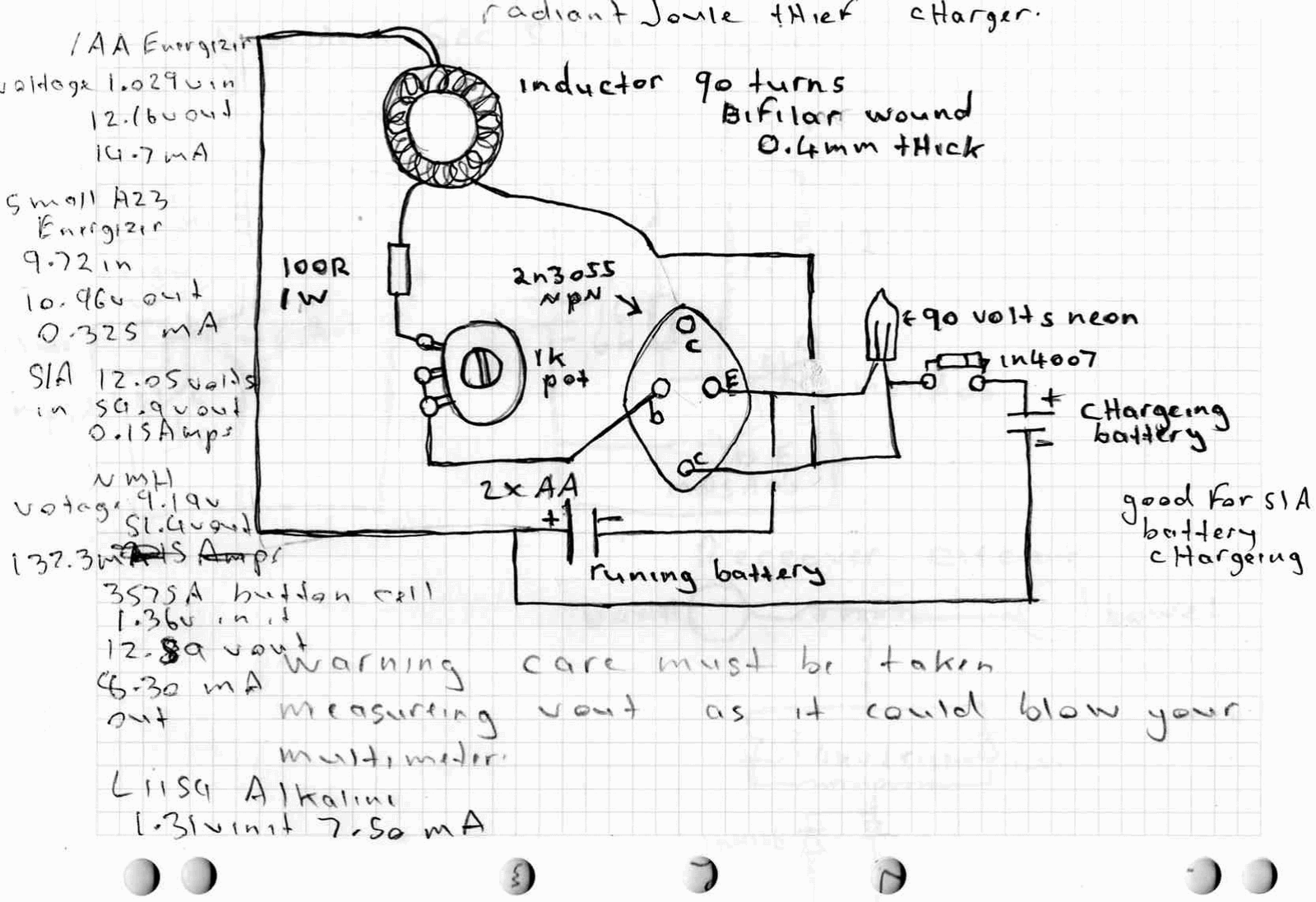
A high power joule thief circuit is explained in this post, which can be constructed by any new hobbyist. Here is the simplified drawing of the radiant joule thief battery charger. The inductor was wound with many turns until...