
LED Electronic roulette

U2 progresses sequentially through its ten outputs (numbered 0 to 9) on pins 1 to 7 and 9 to 11 with each pulse received at the clock input. As each output transitions to a high state, the corresponding LED illuminates and turns off when the output returns to a low state. In this configuration, only eight outputs are utilized, providing two numbers for the spinner mechanism of the house. The circuit can be arranged to produce a sequential lighting pattern of the LEDs, or a staggered combination can be employed, allowing the LEDs to be arranged in a straight line or a circular formation.
The 4046 PLL is a versatile device that allows for modulation of frequency based on external voltage inputs, making it suitable for applications requiring precise timing and frequency control. The choice of components, such as resistors R1, R6, and capacitors C1 and C2, plays a critical role in defining the operational characteristics of the VCO, thereby influencing the overall performance of the circuit. The 4017 decade counter is designed to provide a simple way to drive multiple outputs with a single clock signal, making it ideal for applications like LED displays or indicator lights.
In practice, careful selection of the resistor and capacitor values will determine the frequency response and pulse duration of the output signal. This can lead to various visual effects depending on the arrangement of the LEDs and the timing of the pulses, enhancing the user experience in applications such as games or decorative displays. The integration of the Zener diode in the circuit ensures stable voltage levels, preventing fluctuations that could adversely affect the operation of the VCO and the subsequent output of the 4017 counter. Overall, this circuit exemplifies a practical implementation of a PLL-based timing solution with visual output capabilities.Ul (a 4046 PLL containing a voltage controlled oscillator or VCO, two phase comparators, a source follower, and a Zener diode) is used to produce a low-frequency, pulsed output of about 40 Hz. The VCO's frequency range is determined by R6 and C2, which can be altered by varying the voltage at pin 9.
The rising voltage causes the frequency to rise from zero to threshold and remain at that frequency as long as SI is closed. When SI is opened, Cl discharges slowly through Rl to ground and the voltage falls toward zero. That produces a decreasing pulse rate. The output of Ul at pin 4 is connected to the clock input of U2 (a 4017 decade decoder/driver) at pin 14 via C3.
U2 sequentially advances through each of its ten outputs (0 to 9)—pins 1 to 7, and 9 to 11—with each input pulse. As each output goes high, its associated LED is lighted, and extinguished when it returns to the low state.
Only eight outputs are used in the circuit, giving two numbers to the spinner of the house. The circuit can be set up so that the LED's lights sequence or you can use some staggered combination; the LEDs grouped in a straight line or a circle.
Related Circuits
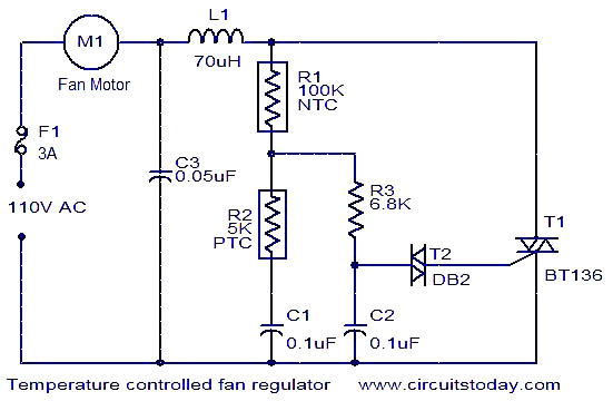
This fan regulator circuit automatically controls the speed of a fan based on temperature. It utilizes two thermistors (R1 and R2) for temperature sensing. The operation is similar to previously published designs, with thermistors replacing the potentiometer. As the...
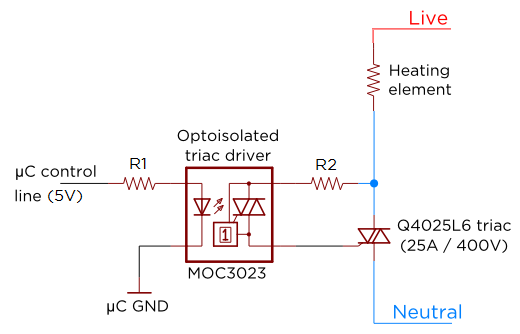
Several individuals have requested clarification on calculating resistor values for a triac circuit. This information may be beneficial for adapting the Sous Vader for custom builds. The circuit in question involves the resistor values R1 and R2 in an...
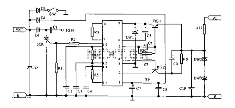
An AC magneto is connected to an external circuit. The output is rectified by diode D1 and stored in capacitor C1. Additional rectification is performed by diodes D4, along with resistors R9 and capacitors C7 and C8, which filter...
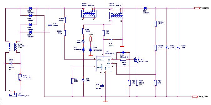
This article outlines a proposed solution for a 200 W power supply utilizing the FSFR2100 Fairchild Power Switch (FPS). The input voltage range is 90 to 265 VRMS, and it features six outputs. The 200 W power supply circuit based...
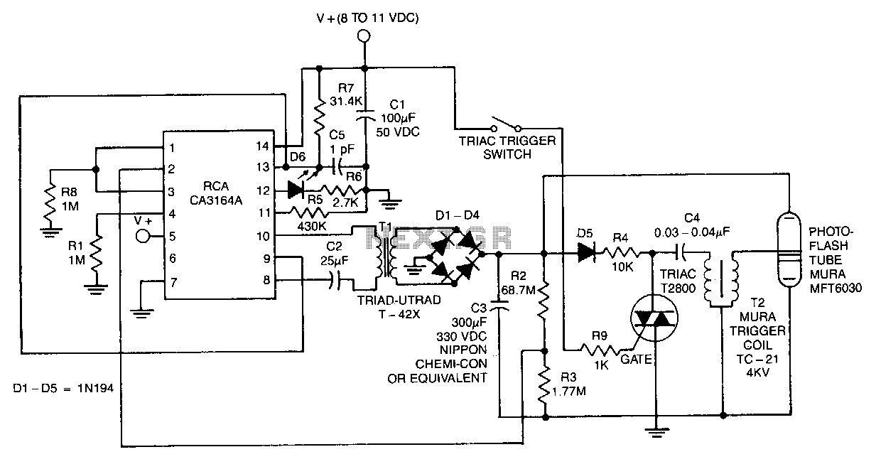
The CA3164A BiMOS control chip operates with a standby current consumption of less than 15 pA while delivering 100 mA of chopped current to the de-to-de converter during the energy-reservoir charging cycle. This chip drives the primary of transformer...
The ISL97676 can be utilized as an LED driver capable of managing six channels of LED current for TFT displays. This driver supports the operation of up to 78 LEDs with a voltage range of 4.5V to 26V, or...