
LED Flashlight circuit with MAX1811
The lamp I used protective circuit of the battery to the mobile phone. Protection circuit disconnects the battery at high voltage drops (it protects against deep discharging) and the charging voltage is too large (defect charger). The protective circuit is not necessary. Collection of lamps are rapidly shrinking for voltages below 3.3 V at a voltage of 3 V is already very small. If you do not use it, connect the batt terminals, and Vout-.
The battery is not necessary to use a new suit as "defective" battery from a mobile phone. For tired batteries mainly increases the internal resistance and then "support arm" GSM phone when posting. The lamp is of the order of less power consumption and battery may still have some time to serve. I put the flashlight on the board according to Figure 2 and 3. The board do more so for what it was fastened in a box. A pack of my friend Dan made from scrap plastic of forex, which are used on billboards. Plates are probably slightly foamed PVC. They are lightweight and a good bond with the abrading cyano. The result of cooperation are two virtually identical lamps. One of them is shown in the photographs.
Additionally, I gained power LED Luxeon Star 1 W with optics they sell at GM. The following illustration is to compare the intensity of nine high-brightness white LEDs (9 cd at 20 mA), total current 180 mA, and LED Luxeon Star, where I set the same current. I shined the two types of LEDs on a white wall from a distance of about 1.5 mA photographed. Luxeon LED light is significantly higher, and this is not supplied with maximum current of 330 mA. Therefore, I recommend to replace the 9 high-brightness LEDs used in the sample Luxeon Star LEDs. The price is comparable. For maximum shine recommend to reduce the resistance R1 and the LED attached to the radiator is enough to heat up.
The described circuit utilizes white LEDs that operate at a forward voltage of approximately 3.3 to 3.4 V. A Li-ion battery is employed to provide the necessary voltage, ensuring optimal energy efficiency. The circuit design incorporates a MAX1811 charging IC, which facilitates the charging of the Li-ion battery via a standard USB port. This design eliminates the need for a dedicated external charger, simplifying the charging process. The MAX1811 is configured to charge a single Li-ion cell to a voltage of 4.2 V, with selectable charging currents of either 100 mA or 500 mA. The connection terminals are specified for the selected voltage and current, with the stability of the circuit being dependent on the quality of the capacitors used (C1 and C2) as per the manufacturer's recommendations.
During the charging process, an LED indicator (LED10) illuminates to signify that charging is occurring, although it only lights up during the constant current phase. Once the battery reaches the target voltage of 4.2 V, the LED turns off, which can be problematic for older batteries with higher internal resistance, as they may reach this voltage prematurely.
A protective circuit is included to safeguard the battery from excessive discharging and overcharging, which is particularly relevant for older batteries. The circuit design emphasizes the use of readily available components, including potentially "defective" batteries from mobile phones, which can still be utilized effectively due to their lower power consumption.
The physical assembly of the flashlight incorporates a lightweight board made from recycled materials, ensuring ease of handling and durability. The Luxeon Star 1 W LED is recommended for use in place of multiple high-brightness LEDs due to its superior light output, making it a more efficient choice for this application. Adjustments to the resistance (R1) may be necessary to optimize the brightness of the Luxeon LED while ensuring adequate thermal management through proper heat sinking.White LEDs have a rated current at a voltage drop of about 3.3 to 3.4 V. It is ideal to be powered from the battery voltage which is slightly larger. Then there is the best energy used. In this I used a flashlight battery, Li-ion battery, which lasts the full brightness of the lamp lit for many hours. Circuit for power LEDs is described here , and I will not repeat its description. More interesting is the charger with the MAX1811 circuit. When designing a lamp for my past experiences like charging as simple as possible. No dedicated external charger that was lost just when it needed to charge the flashlight. You just come on and join lamp standard AB cable to any USB port or cable to temporarily pull out just one unused device. The port is used only to power supply, no software support is not needed. Circuit MAX1811 is designed for charging Li-Ion USB in portable devices. Its great advantage is that, unless the input circuit voltage from the USB port does not consume practically no battery power and may be permanently connected to the battery.
This greatly simplifies the connection. Circuit to charge one cell voltage of 4.1 or 4.2 V and a current of approximately 100 or 500 mA. Here is the connecting terminals 1 and 2 on the + selected voltage of 4.2 V and current of 500 mA. The stability of the circuit are required according to the manufacturer's quality capacitors C1 and C2. Datasheet for circuit, see eg http://www.maxim-ic.com/quick_view2.cfm/qv_pk/2536/ln/en . LED10 light when charging, but unfortunately only in the charging constant current phase. Reaches the battery voltage of 4.2 V, the LED goes out, even if the battery is still fully charged. This is unfortunate especially in older batteries, which due to increased internal resistance of the charging voltage reaches the final soon after the start of charging.
Otherwise I do not have any reservations about charging circuit. The lamp I used protective circuit of the battery to the mobile phone. Protection circuit disconnects the battery at high voltage drops (it protects against deep discharging) and the charging voltage is too large (defect charger). The protective circuit is not necessary. Collection of lamps are rapidly shrinking for voltages below 3.3 V at a voltage of 3 V is already very small.
If you do not use it, connect the batt terminals, and Vout-. The battery is not necessary to use a new suit as "defective" battery from a mobile phone. For tired batteries mainly increases the internal resistance and then "support arm" GSM phone when posting. The lamp is of the order of less power consumption and battery may still have some time to serve. I put the flashlight on the board according to Figure 2 and 3 . The board do more so for what it was fastened in a box. A pack of my friend Dan made ??from scrap plastic of forex, which are used on billboards. Plates are probably slightly foamed PVC. They are lightweight and a good bond with the abrading cyano. The result of cooperation are two virtually identical lamps. One of them is shown in the photographs. Additionally, I gained power LED Luxeon Star 1 W with optics they sell at GM. The following illustration is to compare the intensity of nine high-brightness white LEDs (9 cd at 20 mA), total current 180 mA, and LED Luxeon Star, where I set the same current.
I shined the two types of LEDs on a white wall from a distance of about 1.5 mA photographed. Luxeon LED light is significantly higher, and this is not supplied with maximum current of 330 mA. Therefore, I recommend to replace the 9 high-brightness LEDs used in the sample Luxeon Star LEDs. The price is comparable. For maximum shine recommend to reduce the resistance R1 and the LED attached to the radiator is enough to heat up. 🔗 External reference
Related Circuits
Have you ever seen the stairs to one of the upper stories in your house turn into a waterfall? Or maybe you've come home to find your aquarium fish trying to... The provided description suggests a scenario involving unexpected water...
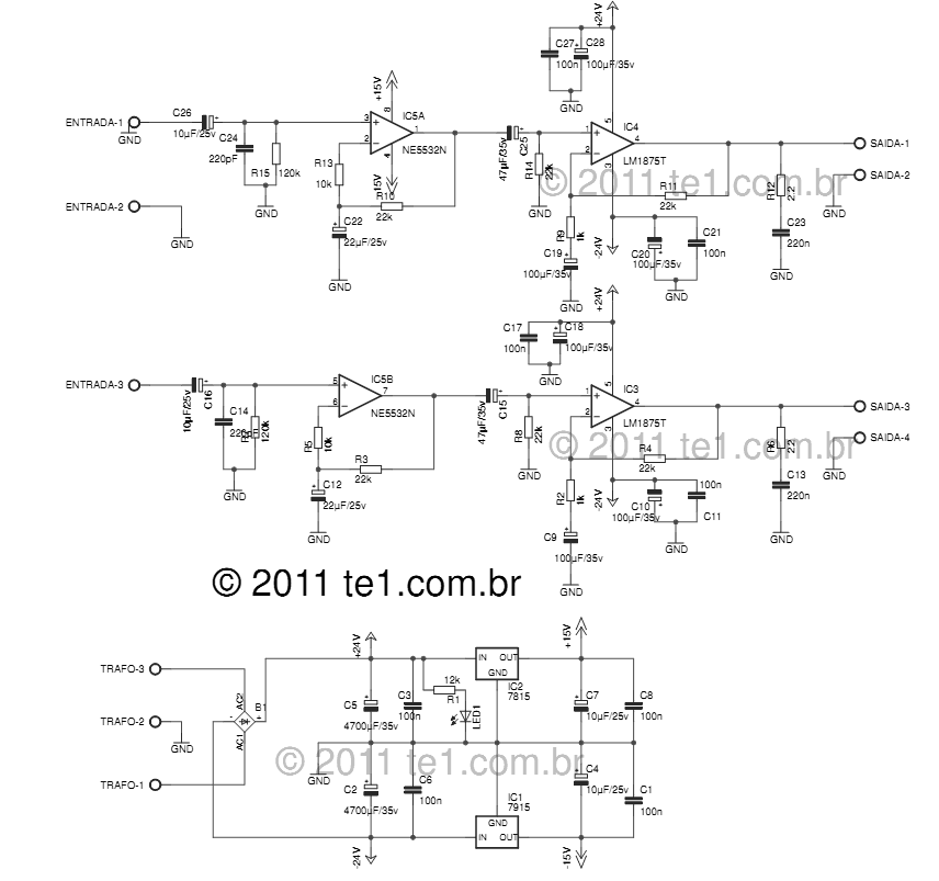
The LM1875 delivers 20 watts into a 4 or 8-ohm load on ±25V supplies. Using an 8-ohm load and ±30V supplies, over 30 watts of power may be delivered. The amplifier is designed to operate with a minimum of...
This is a clap switch designed to avoid false triggering. To activate or deactivate any appliance, a user must clap twice. The circuit changes its output state only when two claps are detected within a specified time frame of...
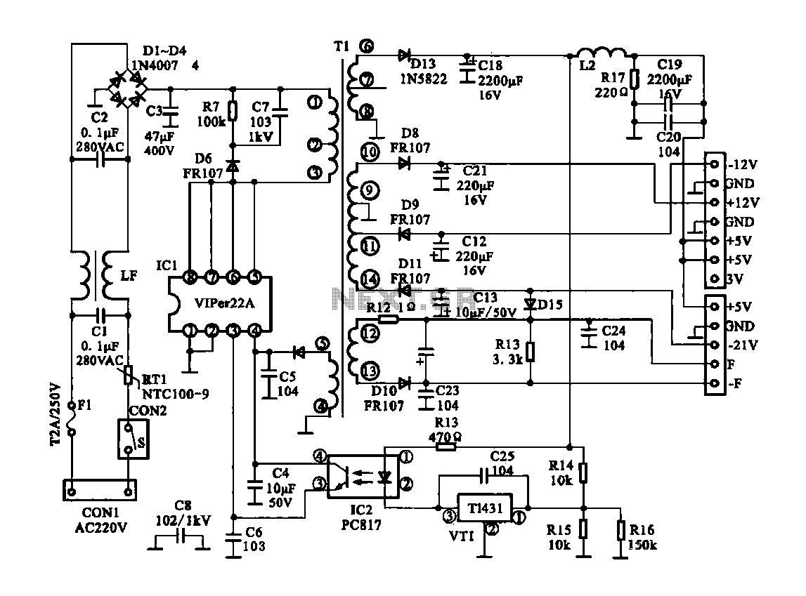
The Dragon ZL-2801A is a DVD machine that utilizes a switching power supply circuit. The circuit primarily consists of an AC input circuit, a rectifier filter wave circuit, an oscillation circuit switch, a switch transformer (Tl), a secondary rectifier,...
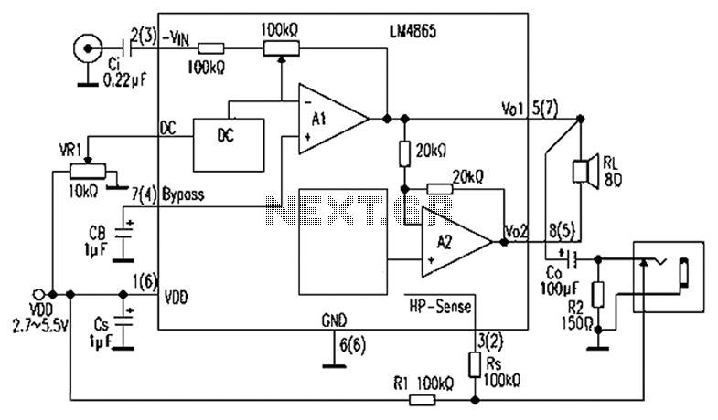
A 750mW bridge-tied load audio amplifier circuit utilizing the LM4065 amplifier is presented below. The LM4865 is available in an 8-pin SO package and an 8-pin mini SMD package. The power supply voltage (VDD) ranges from 2.7V to 5.5V,...

A series of LEDs is used to alert the gardener when plants require watering. By utilizing two conventional digital integrated LEDs along with a series of additional LEDs, this device serves as a practical tool for gardening. It detects...