
Dragon -ZL-2801A DVD machine type switching power supply circuit

1. AC Input Circuit: The AC input circuit includes a power switch (S), a fuse (F1), a mutual inductance filter (LF), and filter capacitors (C1, C2). Its primary function is to filter out interference and noise from the AC input signal.
2. Rectifier Filter Circuit: The 22V AC voltage is processed through a bridge rectifier circuit (D1 to D4) and a filter capacitor (C3), resulting in an output DC voltage of approximately 30V that is sent to the transformer (Tl).
The Dragon ZL-2801A DVD machine's switching power supply circuit is designed for efficiency and reliability. The AC input circuit is essential for protecting the device from voltage spikes and ensuring stable operation. The power switch (S) allows for manual control of the power supply, while the fuse (F1) serves as a safety feature, preventing damage from overcurrent conditions.
The mutual inductance filter (LF) plays a crucial role in attenuating high-frequency noise that may be present in the AC supply. The filter capacitors (C1 and C2) further smooth the input signal, ensuring that the downstream components receive a cleaner voltage.
In the rectifier filter circuit, the bridge rectifier (composed of diodes D1 to D4) converts the AC voltage to DC. This process is critical for providing the necessary power to the DVD machine's internal components. The filter capacitor (C3) stabilizes the output voltage by storing charge and releasing it as needed, resulting in a more consistent DC voltage output. The voltage regulator circuit that follows ensures that the output voltage remains within specified limits, providing reliable power to the system.
The transformer (Tl) is responsible for isolating the power supply and stepping down the voltage as required by different sections of the DVD machine. The switching operation within the circuit allows for efficient power conversion, minimizing energy loss and maximizing performance. Overall, the design and components of the Dragon ZL-2801A's switching power supply circuit are integral to its functionality and longevity.Dragon -ZL-2801A DVD machine type switching power supply circuit It shows Dragon ZL-2801A type DVD machine switching power supply circuit, which is mainly from the AC input cir cuit, a rectifier filter wave circuit, the oscillation circuit switch, switch transformer Tl, secondary rectifier and voltage regulator circuit constituted. 1. AC input circuit AC input circuit from the power switch S, fuse Fl, mutual inductance LF filter and filter capacitor Cl, C2 and the like, its function is to filter the AC input signal interference and noise.
2. Rectifier filter circuit after 22V AC voltage is filtered heap D1 ~ D4 bridge rectifier circuit filter capacitor C3 and processed by a bridge rectifier, and the output DC voltage of about 30V transformer and switch to TIs O feet.
Related Circuits
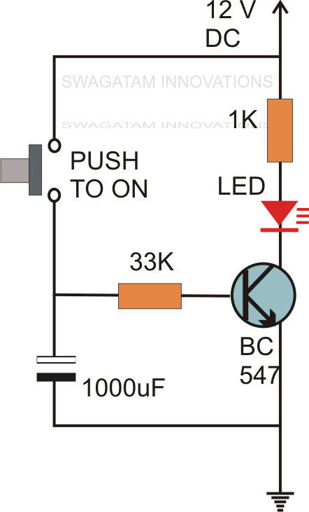
Without the specified delay, the circuit could malfunction or even sustain damage. A capacitor, which is a crucial component of the circuit, is positioned at the other end of the base resistor rather than directly connected to the base...

The touch control screen is a common feature in modern electronic products, typically incorporating a colored liquid crystal display (LCD) with a touch-sensitive interface. This technology is user-friendly and effectively replaces traditional fixed keypads. This document introduces the driving...
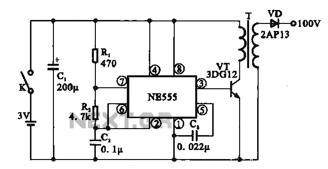
This circuit illustrates a simple boost converter, which is powered by an oscillating signal generated by the NE555 timer. The signal is amplified through a VT transistor to drive a booster transformer. This step-up transformer increases the oscillating signal,...
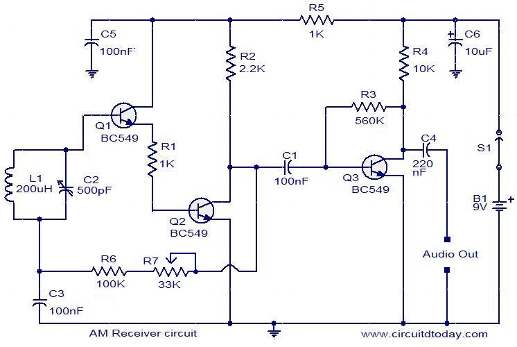
The following circuit illustrates an AM receiver capable of operating within the frequency range of 550 to 1100 KHz. Features include adjustments for sensitivity and selectivity of the circuit. The AM receiver circuit designed for the frequency range of 550...
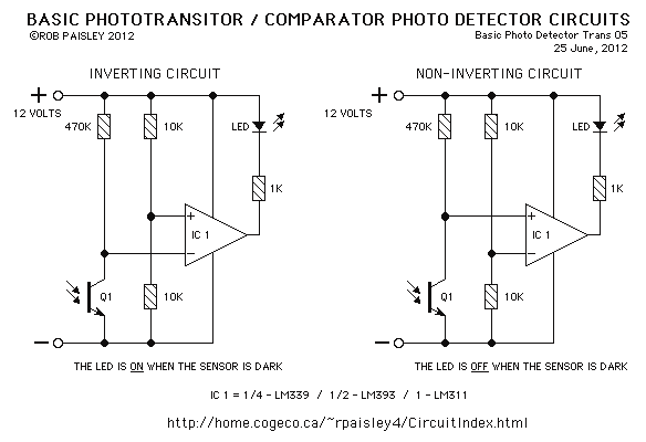
This page features basic, visible light photo-detector circuits that can be used to detect trains. These methods would normally be used with the photo sensor mounted between the rails. The described photo-detector circuits are designed to detect the presence of...
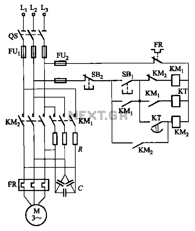
The circuit depicted in Figure 3-35 demonstrates a method for starting a motor that transitions to full voltage through a step-down switching process. This approach provides an uninterruptible power supply, effectively preventing issues related to switching currents that may...