
led How do I amplify a dc voltage that is too weak to trigger the base in a transistor
The circuit design involves utilizing a 2222N NPN transistor, which can amplify low-level signals. The audio signal from the 3.5mm jack is typically a small AC voltage, which may not be adequate to turn on the transistor directly due to its base-emitter voltage threshold, usually around 0.7V. To address this, several solutions can be implemented.
One approach is to employ a simple op-amp circuit configured as a non-inverting amplifier. By connecting the audio signal to the non-inverting input of the op-amp and adjusting the gain through feedback resistors, the output can be increased to a level sufficient to drive the base of the 2222N transistor. The op-amp's power supply should be chosen based on the desired output swing, typically a dual supply of ±5V or ±12V would be appropriate for most applications.
Alternatively, a transformer can be used to step up the voltage. A small audio transformer can be connected to the audio jack output, with the primary winding connected to the audio signal and the secondary winding providing a higher AC voltage. This increased voltage can then be rectified and filtered to provide a DC voltage that can drive the base of the transistor.
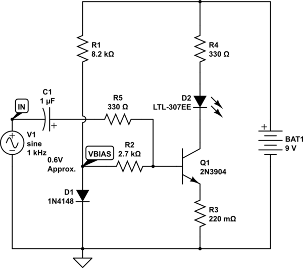
In both cases, it is crucial to ensure that the transistor is adequately biased to operate in the active region. A resistor should be placed between the base of the transistor and the output of the op-amp or transformer to limit the base current. The LED can be connected in series with a current-limiting resistor to the collector of the transistor, allowing it to light up when the transistor is activated.
In summary, to successfully light the LED using the audio signal from a 3.5mm jack, an op-amp or transformer can be utilized to boost the voltage sufficiently to trigger the 2222N transistor, enabling the LED to respond to the audio signal effectively.Take the voltage output from a 3. 5mm audio jack and have it light up an LED according to it`s voltage. I was going to attach the left audio cable to the base of a 2222n transistor which would act as my amplifier to trigger the LED to light. Unfortunately, the voltage reading off the wire is like. 2 or. 02 and isn`t high enough to tri gger the flow. Is there any way to increase the voltage to trigger the transistor or would I have to use a transformer of some sort (or an op amp ) 🔗 External reference
Related Circuits
The ISL97676 can be utilized as an LED driver capable of managing six channels of LED current for TFT displays. This driver supports the operation of up to 78 LEDs with a voltage range of 4.5V to 26V, or...
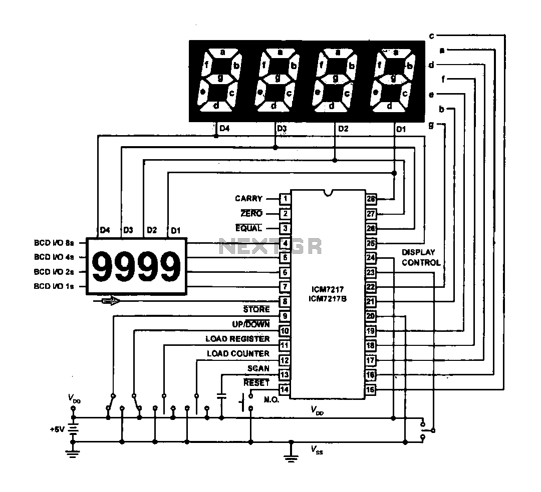
The circuit drives the light-emitting diode in a digital display configuration. The count signal is fed into the ICM7217 chip, which processes the count and subsequently drives the digital display board. The connection between the thumbwheel switches is illustrated...
It is sufficient to explore PWM (Pulse Width Modulation) and digital-to-analog conversion, illustrating how to create a personal electronics workbench for investigating RC (Resistor-Capacitor) filters, charge and discharge curves, pulse generators, timers, and even a simple oscilloscope to understand...
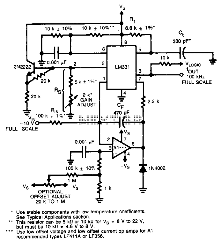
This circuit utilizes a conventional operational amplifier in conjunction with a feedback capacitor (CF) to perform integration. When the output of the integrator exceeds the nominal threshold level at pin 6 of the LM131, it triggers the timing cycle....
The LM317 is capable of providing extremely good load regulation, but a few precautions are needed to obtain maximum performance. For best performance, the programming resistor (R1) should be connected as close to the regulator as possible to minimize...
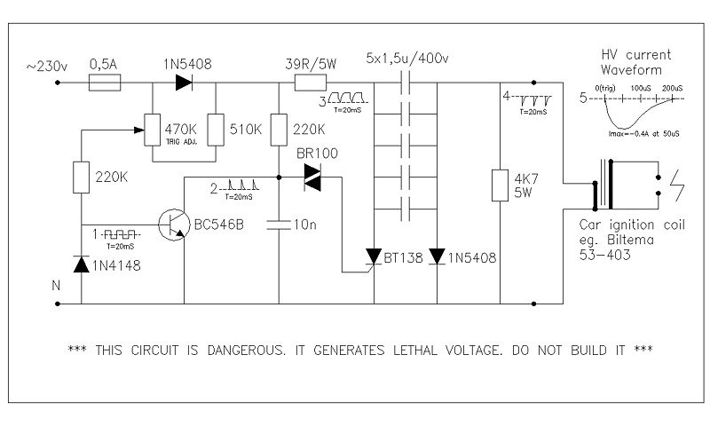
This circuit generates high voltage pulses from a 230 VAC line voltage. The drive end's swing comparator circuit was developed by the creator of this page. The working end is derived from a stroboscope trigger supply circuit. All circuits...